Appendix F
| Optional Input Modules | ||||
|
|
|
|
|
|
|
|
|
|
|
|
| There are many optional input modules and accessories currently available for this | ||||
| projector. Contact your dealer for a complete and | ||||
| NOTE: Always unplug the projector or switcher before installing or removing any optional | ||||
| input module. | ||||
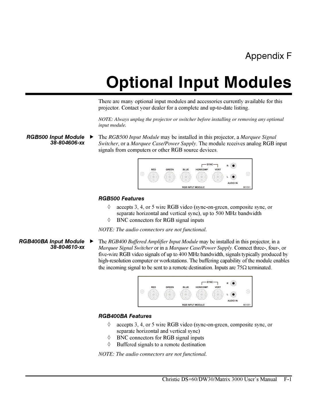
RGB500 Input Module | f The RGB500 Input Module may be installed in this projector, a Marquee Signal | ||||
| Switcher, or a Marquee Case/Power Supply. The module receives analog RGB input | ||||
| signals from computers or other RGB source devices. | ||||
|
|
|
|
|
|
RGB500 Features
◊accepts 3, 4, or 5 wire RGB video
◊BNC connectors for RGB signal inputs
NOTE: The audio connectors are not functional.
RGB400BA Input Module | f The RGB400 Buffered Amplifier Input Module may be installed in this projector, in a | ||||
| Marquee Signal Switcher or in a Marquee Case/Power Supply. Connect | ||||
| |||||
| |||||
| the incoming signal to be sent to a remote destination. Inputs are 75Ω terminated. | ||||
|
|
|
|
|
|
RGB400BA Features
◊accepts 3, 4, or 5 wire RGB video
◊BNC connectors for RGB signal inputs
◊Buffered signals to a remote destination
NOTE: The audio connectors are not functional.
Christie DS+60/DW30/Matrix 3000 User’s Manual