Section 3: Operation
3.7Working with PIP or Seamless Switching
PIP
Options for enabling and controlling PIP and Seamless Switching all reside in the same menu. Note however, that because both features utilize the projector’s double processing capability, PIP and Seamless Switching cannot be used together. For example, fading a pair of PIP images into a new display from a different source is not possible.
For best PIP or Seamless Switching results, use two different signal types* as defined below. Do not mix two signals of the same type.
Signal Type | Description (Input Location) |
#1 | 5 BNCs (RGBHV or YPbPr) |
#2 | DVI - I (analog or digital) |
#3 | Decoded signals (Input 3, Input 4, Composite video, |
| signal via Input 1 BNC connectors or via an analog option card). |
#4 | Analog Option Cards |
#5 | Digital Option Cards |
#6 | Digital Option Cards |
*HD interlaced sources are not recommended for the PIP window.
Other PIP or Seamless Switching tips to keep in mind include:
•When using two digital signals or one analog and one digital, each must be ≤ 165 megapixels.
•When using two analog signals, each must be ≤ 90 megapixels.
•Avoid using an interlaced source in the PIP window
•Seamless switching may affect image quality in some cases
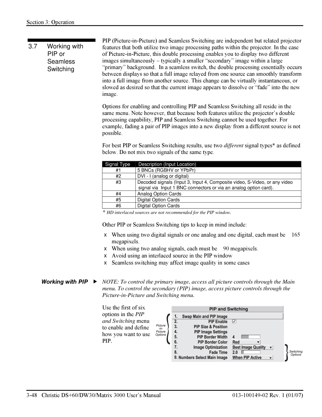
Working with PIP f NOTE: To control the primary image, access all picture controls through the Main menu. To control the secondary (PIP) image, access picture controls through the
Use the first of six options in the PIP and Switching menu to enable and define how you want to use PIP.