Section 3: Operation
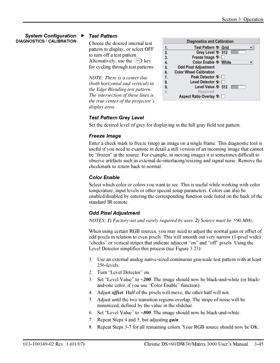
System Configuration | f Test Pattern |
DIAGNOSTICS / CALIBRATION | Choose the desired internal test |
| pattern to display, or select OFF |
| to turn off a test pattern. |
| Alternatively, use the Test key |
| for cycling through test patterns. |
| NOTE: There is a center line |
| (both horizontal and vertical) in |
| the Edge Blending test pattern. |
| The intersection of these lines is |
| the true center of the projector’s |
| display area. |
| Test Pattern Grey Level |
| Set the desired level of grey for displaying in the full gray field test pattern. |
| Freeze Image |
| Enter a check mark to freeze (stop) an image on a single frame. This diagnostic tool is |
| useful if you need to examine in detail a still version of an incoming image that cannot |
| be “frozen” at the source. For example, in moving images it is sometimes difficult to |
| observe artifacts such as external |
| checkmark to return back to normal. |
| Color Enable |
| Select which color or colors you want to see. This is useful while working with color |
| temperature, input levels or other special setup parameters. Colors can also be |
| enabled/disabled by entering the corresponding function code listed on the back of the |
| standard IR remote. |
| Odd Pixel Adjustment |
| NOTES: 1) |
| When using certain RGB sources, you may need to adjust the normal gain or offset of |
| odd pixels in relation to even pixels. This will smooth out very narrow |
| “checks” or vertical stripes that indicate adjacent “on” and “off” pixels. Using the |
| Level Detector simplifies this process (see Figure 3.23): |
| 1. Use an external analog |
| |
| 2. Turn “Level Detector” on. |
| 3. Set “Level Value” to ~200. The image should now be |
| |
| 4. Adjust offset. Half of the pixels will move, the other half will not. |
| 5. Adjust until the two transition regions overlap. The stripe of noise will be |
| minimized, defined by the value in the slidebar. |
| 6. Set “Level Value” to ~800. The image should now be |
| 7. Repeat Steps 4 and 5, but adjusting gain. |
| 8. Repeat Steps |
| Christie DS+60/DW30/Matrix 3000 User’s Manual |