Section 2: Installation and Setup
| Regardless of how it is assigned, once a projector has a valid and unique address it | ||||||||||||
| will respond to commands sent to this address. To determine the projector’s current IP | ||||||||||||
| address, consult the Status or Communications menus. | ||||||||||||
| Refer to Section 3 for further information about setting up and using a projector | ||||||||||||
| connected via Ethernet. | ||||||||||||
Connecting Multiple | f | ||||||||||||
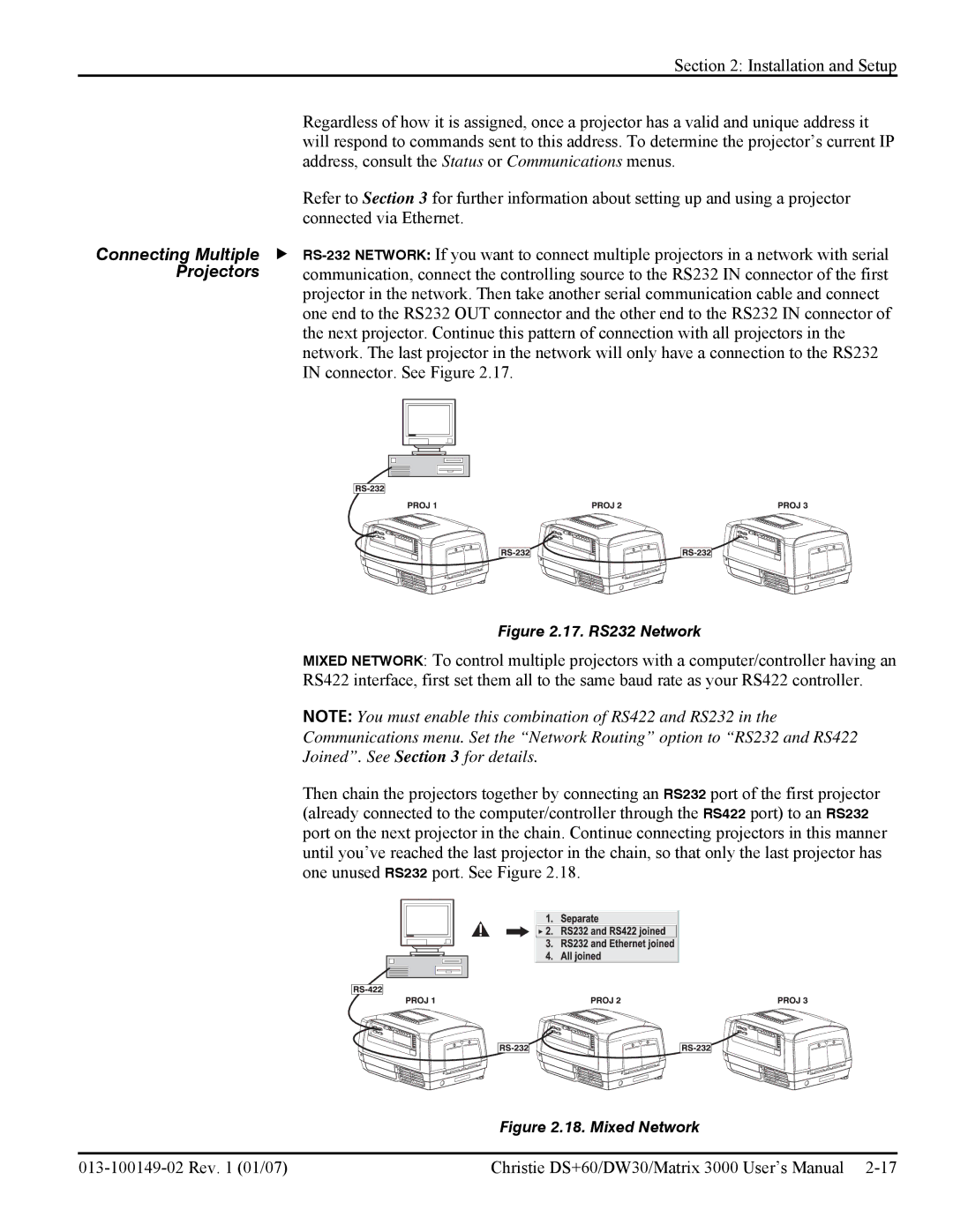
Projectors | communication, connect the controlling source to the RS232 IN connector of the first | ||||||||||||
| projector in the network. Then take another serial communication cable and connect | ||||||||||||
| one end to the RS232 OUT connector and the other end to the RS232 IN connector of | ||||||||||||
| the next projector. Continue this pattern of connection with all projectors in the | ||||||||||||
| network. The last projector in the network will only have a connection to the RS232 | ||||||||||||
| IN connector. See Figure 2.17. | ||||||||||||
|
|
|
|
|
|
|
|
|
|
|
|
|
|
|
|
|
|
|
|
|
|
|
|
|
|
|
|
|
|
|
|
|
|
|
|
|
|
|
|
|
|
|
|
|
|
|
|
|
|
|
|
|
|
|
|
|
|
|
|
|
|
|
|
|
|
|
|
|
|
|
|
|
|
|
|
|
|
|
|
|
|
|
|
|
|
|
|
|
|
|
|
|
|
|
|
|
|
|
|
|
|
|
|
|
|
|
|
|
|
|
|
|
|
|
|
|
|
|
|
|
|
|
|
|
|
|
|
|
|
|
|
|
|
|
|
|
|
|
|
|
|
|
|
|
|
|
|
|
|
|
|
|
|
|
|
|
|
|
|
|
|
|
|
|
|
|
|
|
|
|
|
|
|
|
|
|
|
|
|
|
|
|
|
|
|
|
|
|
|
|
|
|
|
|
|
Figure 2.17. RS232 Network
MIXED NETWORK: To control multiple projectors with a computer/controller having an
RS422 interface, first set them all to the same baud rate as your RS422 controller.
NOTE: You must enable this combination of RS422 and RS232 in the
Communications menu. Set the “Network Routing” option to “RS232 and RS422
Joined”. See Section 3 for details.
Then chain the projectors together by connecting an RS232 port of the first projector (already connected to the computer/controller through the RS422 port) to an RS232 port on the next projector in the chain. Continue connecting projectors in this manner until you’ve reached the last projector in the chain, so that only the last projector has one unused RS232 port. See Figure 2.18.
Figure 2.18. Mixed Network
Christie DS+60/DW30/Matrix 3000 User’s Manual |