Manuals
/
Brands
/
Personal Care
/
Mobility Aid
/
Invacare
/
Personal Care
/
Mobility Aid
Invacare
FDX, FDX-CG, FDX-MCG
- page 58
1
58
100
100
Download
100 pages, 5.18 Mb
6 MOTOR LOCKS/WHEEL LOCKS
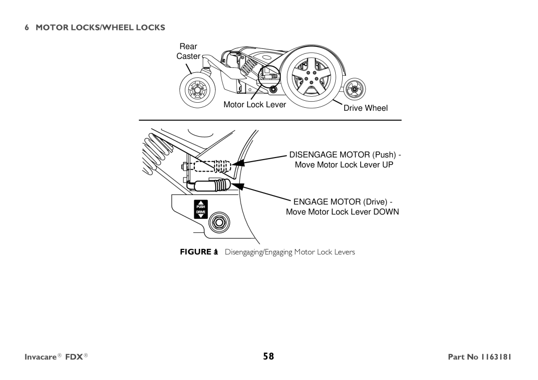
Invacare® FDX®
58
Part No 1163181
FIGURE
1
Disengaging/Engaging Motor Lock Levers
Rear
Caster
Drive Wheel
DISENGAGE MOTOR (Push) -
Move Motor Lock Lever UP
ENGAGE MOTOR (Drive) -
Move Motor Lock Lever DOWN
Motor Lock Lever
Contents
Main
Page
Page
Page
Page
Page
1 General
!
1.2 Reference Documents
1.3 Global Limited Warranty (Excluding Canada)
MANUAL PART NUMBER
1 GENERAL
Part No 1163181 9Invacare FDX
1 GENERAL
Invacare FDX 10 Part No 1163181
1.4 Canada Limited Warranty
2 Safety
!
Page
Page
Page
Page
Page
Page
Page
Page
Page
Page
Page
Page
Page
Page
Page
Page
Page
3 Label Locations
Wheelchairs without TRRO.
Wheelchairs with TRRO
Wheelchairs with Running Lights
WARNING
4 Technical Data
4.1 Typical Product Parameters Models Overall Dimensions
Seat
Wheels Driving
Weight
5 Wheelchair Operation
Page
Using the Joystick to Drive the Wheelchair
Page
5.3 SPJ+, MK6i SPJ+ w/PSS and MK6i SPJ+ w/ACC Joystick Switches and Indicators
On/Off Button
Speedometer
Speed Control Buttons
Joystick
Charger/Programming Input
Information Gauge Display
Service Indicator
5.4 MPJ+ Joystick Switches and Indicators On/Off - Drive Select Toggle Switch
Page
LCD DISPLAY
ITEM DESCRIPTION
User Settings
User Settings Set Date and Time Battery Voltage Connected Devices
Page
Programmable Mono Ports 1 and 2 with External Mode Switch
Remote On/Off Switch
SPJ+, SPJ+ w/PSS and SPJ+ w/ACC Joysticks
MPJ+ Joystick
Page
Page
TOOL QUANTITY COMMENTS
Page
6 Motor Locks/Wheel Locks
Page
Page
7 Transport Ready Option (TRRO)
Page
Page
Page
Page
DETAIL A - PELVIC BELT
DETAIL B
RATING DESCRIPTION
Page
Page
8 Setup/Maintenance
Page
Inspect/Adjust Monthly
Inspect/Adjust Periodically
Page
Page
Inspect/Adjust Every 18 Months
Page
FOR WHEELCHAIRS USING GP34 BATTERIES
TOOL QTY COMMENTS
Removing/Installing the Front Battery
Reverse this procedure to install the front battery.
Page
Page
DETAIL A DETAIL B
Page
Rear Battery
FIGURE5 Anti-Tippers
8.9 Adjusting Forks
This procedure must be performed by a qualified technician. This procedure applies to both Forks.
Page
MPJ+ Joysticks
FIGURE9 Disconnecting/Connecting the Joysticks - MPJ+ Joysticks
connector cap and between network connectors.
9 Troubleshooting
DISPLAY DESCRIPTION DEFINITION COMMENTS
Service Indicator Light
Page
Page
SYMPTOM PROBABLE CAUSE SOLUTIONS
9.3 Checking Battery Charge Level
DONT DO