PROCEDURE 3 | FRONT RIGGINGS |
F R O N T
R
I
G G I N G S
Replacing
NOTE: Observe the position of the current telescoping front rigging support before removal to ensure correct position of new support assembly.
1.Remove the existing telescoping front rigging sup- port from the wheelchair.
2.Install the new telescoping front rigging support into the wheelchair.
3.Adjust the telescoping front rigging support. Refer to
ADJUSTING TELESCOPING FRONT RIGGING SUPPORT in this procedure of the manual.
ADJUSTING REMOVABLE
FOOTBOARD
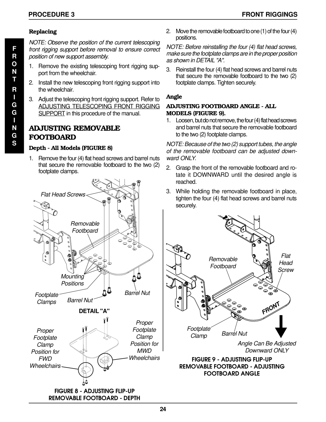
Depth - All Models (FIGURE 8)
1.Remove the four (4) flat head screws and barrel nuts that secure the removable footboard to the two (2) footplate clamps.
Flat Head Screws
Removable
Footboard
2.Move the removable footboard to one (1) ofthe four (4) positions.
NOTE: Before reinstalling the four (4) flat head screws, make sure the footplate clamps are in the proper position as shown in DETAIL "A".
3.Reinstall the four (4) flat head screws and barrel nuts that secure the removable footboard to the two (2) footplate clamps. Tighten securely.
Angle
ADJUSTING FOOTBOARD ANGLE - ALL MODELS (FIGURE 9).
1.Loosen,butdonotremove,thefour(4)flatheadscrews and barrel nuts that secure the removable footboard to the two (2) footplate clamps.
NOTE: Because of the two (2) support tubes, the angle of the removable footboard can be adjusted down- ward ONLY.
2.Grasp the front of the removable footboard and ro- tate it DOWNWARD until the desired angle is reached.
3.While holding the removable footboard in place, tighten the four (4) flat head screws and barrel nuts securely.
Removable
Flat
Footboard
Head
| Mounting |
| Positions |
Footplate | Barrel Nut |
|
Clamps | Barrel Nut |
| DETAIL "A" |
Screw
Proper
Footplate
Clamp
Position for
FWD
Wheelchairs
Proper
Footplate
Clamp
Position for
MWD
![]() Wheelchairs
Wheelchairs
Footplate
Clamp | Barrel Nut |
| |
| Angle Can Be Adjusted |
| Downward ONLY |
FIGURE 9 - ADJUSTING FLIP-UP
REMOVABLE FOOTBOARD - ADJUSTING
FOOTBOARD ANGLE
FIGURE 8 - ADJUSTING FLIP-UP
REMOVABLE FOOTBOARD - DEPTH
24
