PROCEDURE 10 | BATTERIES | ||
|
|
|
|
B A
9.Install the battery box(es) into the wheelchair. Refer to INSTALLING/REMOVINGBATTERYBOX(ES) in the PROCEDURE 11 - FWD MODELS or PROCE- DURE 12 - MWD MODELS of this manual.
NOTE:NewBattery(ies)MUSTbefullychargedBEFORE using, otherwise the life of the battery(ies) will be reduced.
10.If necessary, charge the battery(ies). Refer to CHARGING BATTERIES in the PROCEDURE 11 - FWD MODELS or PROCEDURE 12 - MWD MOD- ELS of this manual.
T T E R I E S
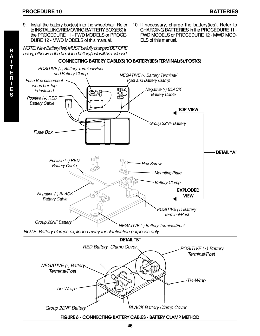
CONNECTING BATTERY CABLE(S) TO BATTERY(IES) TERMINAL(S)/POST(S)
POSITIVE (+) Battery Terminal/Post |
| |
and Battery Clamp | NEGATIVE | |
| ||
Fuse Box placement | Post and Battery Clamp | |
when box top | Negative | |
is installed | ||
Battery Cable | ||
Positive (+) RED | ||
| ||
Battery Cable |
| |
| TOP VIEW | |
| Group 22NF Battery | |
Fuse Box |
|
DETAIL “A”
Positive (+) RED | Hex Screw | |
Battery Cable | ||
|
Mounting Plate
Battery Clamp
EXPLODED
Negative
Battery Cable
POSITIVE (+) Battery
Terminal/Post
Group 22NF Battery
NEGATIVE
NOTE: Battery clamps exploded away for clarification purposes only.
DETAIL “B” |
|
RED Battery Clamp Cover | POSITIVE (+) Battery |
| |
| Terminal/Post |
NEGATIVE (-) Battery
Terminal/Post
Tie-Wrap
Group 22NF Battery | BLACK Battery Clamp Cover |
FIGURE 6 - CONNECTING BATTERY CABLES - BATTERY CLAMP METHOD
46