PROCEDURE 12 | MWD WHEELCHAIRS |
M W D
W
H
E
E
L
C H A I R S
1.Examine battery clamps and terminals for corrosion.
2.If applicable, verify that the plastic caps are in place over the battery cell holes.
3.Cut the tie wraps around the terminal caps/covers.
4.Slide the terminal cap/cover up the wire to expose the battery terminal.
5.Clean the terminals and inside the battery clamps by using a battery cleaning tool, wire brush, or medium grade sand paper.
NOTE: When done, these areas should be shiny, not dull.
6.Carefully dust off all metal particles.
7.Slidetheterminalcap/coverbackdownthewiretocover the battery terminal.
8.Secure the terminal cap/cover using NEW tie wraps.
INSTALLING/REMOVING BATTERY BOXES (FIGURE 5)
NOTE: To remove the battery boxes from the wheelchair, reverse the following procedure.
NOTE: If the wheelchair is equipped with the removeable footboard AND it is installed in the heighest position, it is necessary to remove the footboard plate BEFORE removing the battery boxes. Refer to PRE-
PARING THE REMOVEABLE FOOTBOARD FOR WHEELCHAIR TRANSPORTATION in PROCEDURE 3 of this manual.
NOTE: Motors should be in the engaged position when removing/installingbatteries.Referto ENGAGING/DISEN- GAGING MOTORS in PROCEDURE 8 of this manual.
1.Verify that the ON/OFF switch on the joystick is in the OFF position.
2.If necessary, remove the front and rear shrouds. Refer to REMOVING/INSTALLING SHROUDS in PROCE- DURE 9 of this manual.
WARNING
3.Position the battery boxes onto the battery tray in the following order:
A.FRONT Battery Box.
B.REAR Battery Box.
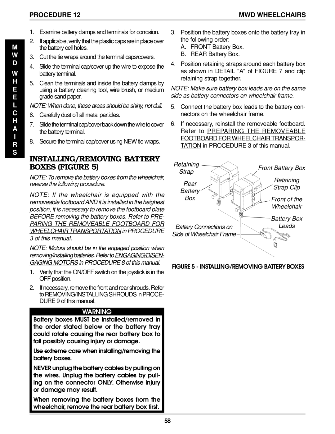
4.Position retaining straps around each battery box as shown in DETAIL "A" of FIGURE 7 and clip retaining strap together.
NOTE: Make sure battery box leads are on the same side as battery connectors on wheelchair frame.
5.Connect the battery box leads to the battery con- nectors on the wheelchair frame.
6.If necessary, reinstall the removeable footboard. Refer to PREPARING THE REMOVEABLE FOOTBOARD FOR WHEELCHAIR TRANSPOR- TATION in PROCEDURE 3 of this manual.
Retaining | Front Battery Box | |
Strap | ||
| ||
Rear | Retaining | |
Strap Clip | ||
Battery | ||
| ||
Box | Front of the | |
| Wheelchair | |
| Battery Box | |
Battery Connections on | Leads | |
Side of Wheelchair Frame |
|
FIGURE 5 - INSTALLING/REMOVING BATTERY BOXES
Battery boxes MUST be installed/removed in the order stated below or the battery tray could rotate causing the rear battery box to fall possibly causing injury or damage.
Use extreme care when installing/removing the battery boxes.
NEVER unplug the battery cables by pulling on the wires. Unplug the battery cables by pull- ing on the connector ONLY. Otherwise injury or damage may result.
When removing the battery boxes from the wheelchair, remove the rear battery box first.
58