MWD WHEELCHAIRS | PROCEDURE 12 |
FOLDING.
1.HIGH BACK CAPTAIN'S SEATS ONLY - Discon- nect the limit switch. Refer to DISCONNECTING/ CONNECTING LIMIT SWITCH in PROCEDURE 6 of this manual.
Refer to BATTERY TRAYS - REMOVABLE BATTERY TRAYS and INSTALLING/REMOVING BATTERY BOXES in this procedure of the manual.
2.Remove the Captain's Seat. Refer to REMOVING/ INSTALLING CAPTAIN'S SEAT in PROCEDURE 5 of this manual.
3.Remove the shrouds. Refer to REMOVING/IN- STALLING SHROUDS in PROCEDURE 9 of this manual.
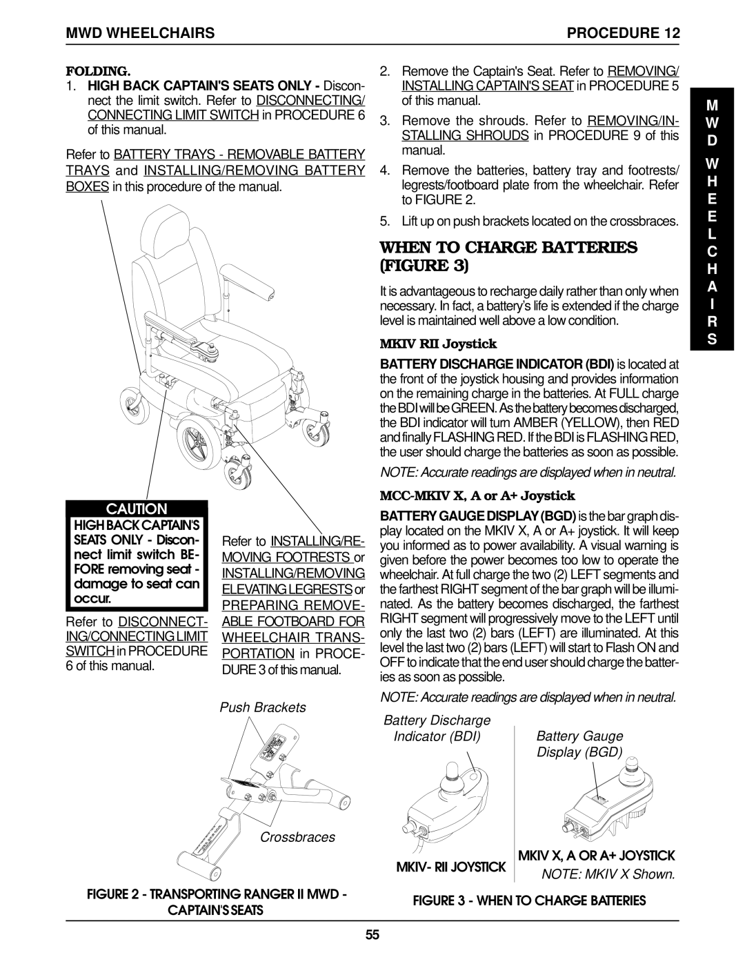
4.Remove the batteries, battery tray and footrests/ legrests/footboard plate from the wheelchair. Refer to FIGURE 2.
5.Lift up on push brackets located on the crossbraces.
WHEN TO CHARGE BATTERIES (FIGURE 3)
It is advantageous to recharge daily rather than only when necessary. In fact, a battery’s life is extended if the charge level is maintained well above a low condition.
MKIV RII Joystick
BATTERY DISCHARGE INDICATOR (BDI) is located at the front of the joystick housing and provides information on the remaining charge in the batteries. At FULL charge theBDIwillbeGREEN.Asthebatterybecomesdischarged, the BDI indicator will turn AMBER (YELLOW), then RED and finally FLASHING RED. If the BDI is FLASHING RED, the user should charge the batteries as soon as possible.
NOTE: Accurate readings are displayed when in neutral.
MCC-MKIV X, A or A+ Joystick
M W D
W H E E L C H A I R S
CAUTION
HIGHBACKCAPTAIN'S SEATS ONLY - Discon- nect limit switch BE- FORE removing seat - damage to seat can occur.
Refer to DISCONNECT-
ING/CONNECTING LIMIT SWITCH in PROCEDURE 6 of this manual.
Refer to INSTALLING/RE- MOVING FOOTRESTS or
INSTALLING/REMOVING ELEVATINGLEGRESTS or
PREPARING REMOVE- ABLE FOOTBOARD FOR WHEELCHAIR TRANS- PORTATION in PROCE- DURE 3 of this manual.
BATTERY GAUGE DISPLAY (BGD) is the bar graph dis- play located on the MKIV X, A or A+ joystick. It will keep you informed as to power availability. A visual warning is given before the power becomes too low to operate the wheelchair. At full charge the two (2) LEFT segments and the farthest RIGHT segment of the bar graph will be illumi- nated. As the battery becomes discharged, the farthest RIGHT segment will progressively move to the LEFT until only the last two (2) bars (LEFT) are illuminated. At this level the last two (2) bars (LEFT) will start to Flash ON and OFF to indicate that the end user should charge the batter- ies as soon as possible.
NOTE: Accurate readings are displayed when in neutral.
Push Brackets
Crossbraces
FIGURE 2 - TRANSPORTING RANGER II MWD -
CAPTAIN'S SEATS
Battery Discharge
Indicator (BDI) Battery Gauge
Display (BGD)
MKIV- RII JOYSTICK | MKIV X, A OR A+ JOYSTICK | |
NOTE: MKIV X Shown. | ||
|
FIGURE 3 - WHEN TO CHARGE BATTERIES
55