ELECTRONICS | PROCEDURE 6 |
This Procedure Includes the Following:
Preparing MKIV Joystick for Use Repositioning MKIV Joystick Disconnecting/Connecting Limit Switch Repositioning Battery Charger Connector Fuse Replacement
WARNING
AfterANYadjustments,repairorserviceandBEFORE use, make sure all attaching hardware is tightened securely - otherwise injury or damage may result.
PREPARING MKIV JOYSTICK FOR USE (FIGURE 1)
NOTE: The MKIV joystick is factory installed on the right side of the wheelchair. To reposition the MKIV joystick onto the left side of the wheelchair, perform one (1) of the follow- ing: INTEGRATED SLING SEAT WHEELCHAIRS - RE- POSITIONING MKIV JOYSTICK in this procedure of the manual or CAPTAIN'S SEAT MODEL WHEELCHAIRS - have the joystick repositioned by an authorized Invacare dealer or qualified technician.
1.Turn the lever on the adjustment lock to release the adjustment lock from joystick mounting tube.
2.Slide joystick mounting tube to the desired position.
3.Turn the lever on the adjustment lock to secure the adjustment lock to the joystick mounting tube.
MKIV Joystick
Adjustment
JoystickLock
MountingTube
FIGURE 1 - PREPARING MKIV JOYSTICK FOR USE
REPOSITIONING MKIV JOYSTICK
Integrated Sling Seat Models (FIGURE 2)
1.Turn the lever on the adjustment lock to release the adjustment lock from joystick mounting tube (tube).
2.Remove the joystick from the wheelchair.
3.Remove the three (3) hex screws that secure joystick mountingbracket(bracket),thethreadedholehalfclamp and the opened hole half clamp to the arm tube.
4.Reposition the threaded hole half clamp and opened hole half clamp on the opposite arm tube. Make sure threaded hole half clamp is on the inside of arm tube.
5.While holding the two (2) half clamps, install the front hex screw into the two (2) half clamps. Securely tighten.
6.Lineupmountingholesofthejoystickmountingbracket with the mounting holes in the two (2) half clamps.
7.Secure the joystick mounting bracket to the two (2) half clamps with the remaining two (2) hex screws.
8.Slide tube through the bracket to the desired position.
9.Slide adjustment lock over end of tube and secure ad- justment lock to tube by turning lever on adjustment lock.
NOTE: If adjustment lock does not fit over tube, rotate 180o.
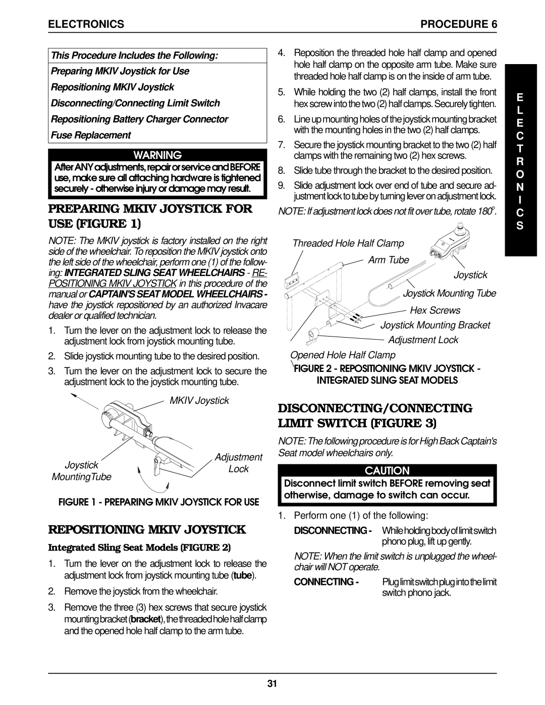
Threaded Hole Half Clamp
Arm Tube
Joystick
![]() Joystick Mounting Tube
Joystick Mounting Tube
Hex Screws
Joystick Mounting Bracket
Adjustment Lock
Opened Hole Half Clamp
FIGURE 2 - REPOSITIONING MKIV JOYSTICK -
INTEGRATED SLING SEAT MODELS
DISCONNECTING/CONNECTING LIMIT SWITCH (FIGURE 3)
NOTE: The following procedure is for High Back Captain's Seat model wheelchairs only.
CAUTION
Disconnect limit switch BEFORE removing seat otherwise, damage to switch can occur.
1.Perform one (1) of the following: DISCONNECTING - Whileholdingbodyoflimitswitch
phono plug, lift up gently.
NOTE: When the limit switch is unplugged the wheel- chair will NOT operate.
CONNECTING - Pluglimitswitchplugintothelimit switch phono jack.
E L E C T R O N I C S
31