SSG 20 Hardware Installation and Configuration Guide
T1 Interface
FCC Part 68 - TIA 968
Industry Canada
UL
Connectors
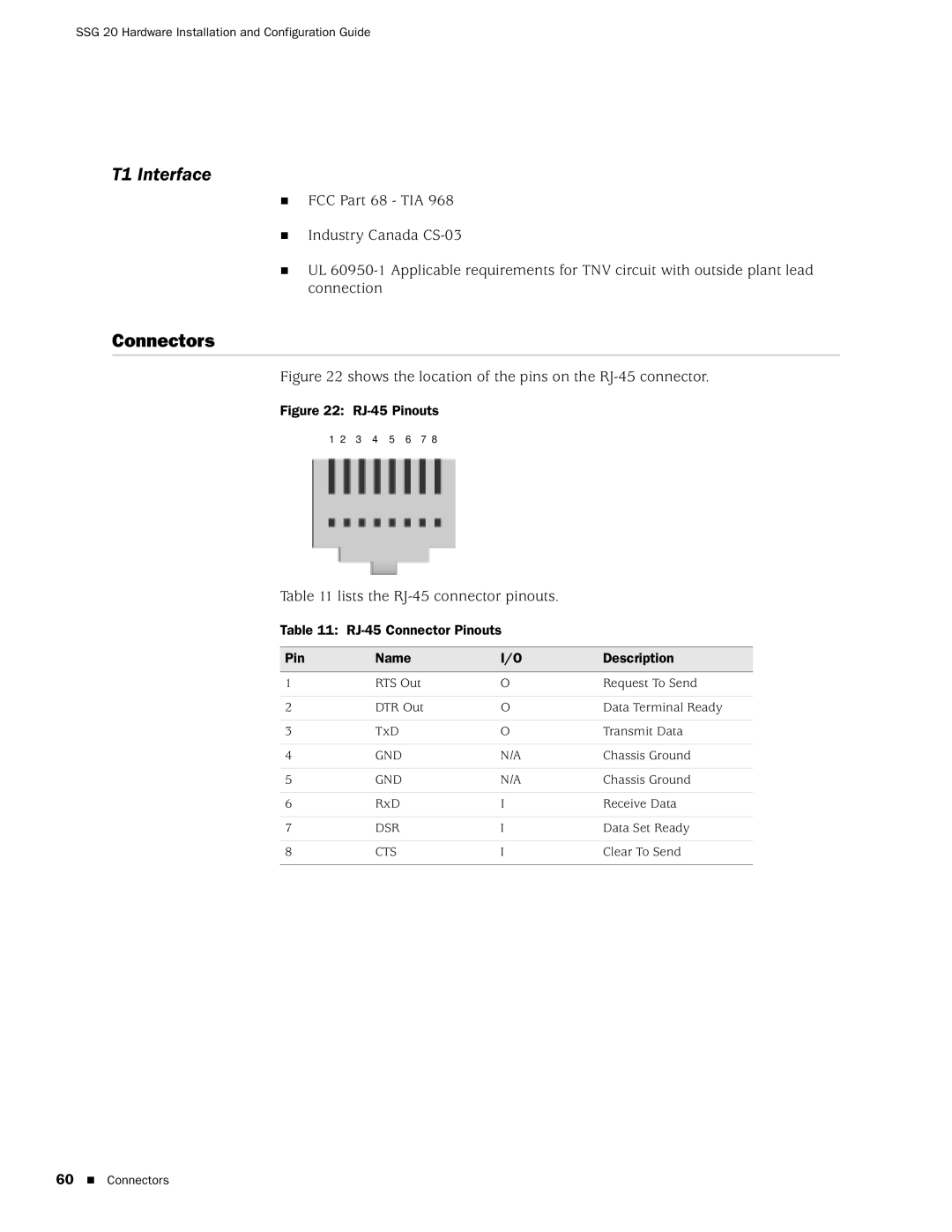
Figure 22 shows the location of the pins on the RJ-45 connector.
Figure 22: RJ-45 Pinouts
1 2 3 4 5 6 7 8
Table 11 lists the RJ-45 connector pinouts.
Table 11: RJ-45 Connector Pinouts
Pin | Name | I/O | Description |
|
|
|
|
1 | RTS Out | O | Request To Send |
|
|
|
|
2 | DTR Out | O | Data Terminal Ready |
|
|
|
|
3 | TxD | O | Transmit Data |
|
|
|
|
4 | GND | N/A | Chassis Ground |
|
|
|
|
5 | GND | N/A | Chassis Ground |
|
|
|
|
6 | RxD | I | Receive Data |
|
|
|
|
7 | DSR | I | Data Set Ready |
|
|
|
|
8 | CTS | I | Clear To Send |
|
|
|
|
60 Connectors