CONTROLS, INDICATORS AND CONNECTORS
Front Section
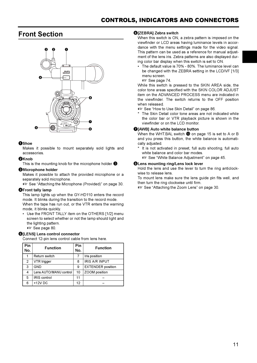
3 2 1
4
8
7
56
1Shoe
Makes it possible to mount separately sold lights and accessories.
2Knob
This is the mounting knob for the microphone holder 3.
3Microphone holder
Makes it possible to attach the provided microphone or a separately sold microphone.
X See “Attaching the Microphone (Provided)” on page 30.
4Front tally lamp
This lamp lights up when the
•Use the FRONT TALLY item on the OTHERS [1/2] menu screen to select whether or not the lamp should light and the lighting pattern.
X See page 80.
5[LENS] Lens control connector
Connect
Pin | Function | Pin | Function | |
No. | No. | |||
|
| |||
1 | Return switch | 7 | Iris position | |
|
|
|
| |
2 | VTR trigger | 8 | IRIS A/R INPUT | |
|
|
|
| |
3 | GND | 9 | EXTENDER position | |
|
|
|
| |
4 | Lens AUTO/MANU control | 10 | ZOOM position | |
|
|
|
| |
5 | IRIS control | 11 | – | |
|
|
|
| |
6 | +12V DC | 12 | – |
6[ZEBRA] Zebra switch
When this switch is ON, a zebra pattern is imposed on the viewfinder or LCD areas having luminance levels in accor- dance with the menu settings made for the video signal. This pattern can be used as a reference for manual adjust- ment of the lens iris. Zebra patterns are also displayed dur- ing color bar display when this switch is set to ON.
•The default value is 70% - 80%. The luminance level can be changed with the ZEBRA setting in the LCD/VF [1/3] menu screen.
X See page 74.
While this switch is pressed to the SKIN AREA side, the color tone areas specified with the SKIN COLOR ADJUST item on the ADVANCED PROCESS menu are indicated in the viewfinder. The switch returns to the OFF position when released.
X See “How to Use Skin Detail” on page 86.
*The Skin Detail color tone areas are not indicated while the color bar or VTR playback picture is shown in the viewfinder or on the LCD monitor.
7[AWB] Auto white balance button
When the WHT.BAL switch c on page 15 is set to A or B and you press this button, the white balance is automati- cally adjusted.
*It is not activated in preset, full auto shooting, full auto white balance and color bar modes.
X See “White Balance Adjustment” on page 45.
8Lens mounting ring/Lens lock lever
Hold the lens and use the lever to turn the ring anticlock- wise to release lens.
To mount lens make sure the lens guide pin fits well, and then turn the ring clockwise until firm.
X See “Attaching the Zoom Lens” on page 30.
11