CONTROLS, INDICATORS AND CONNECTORS
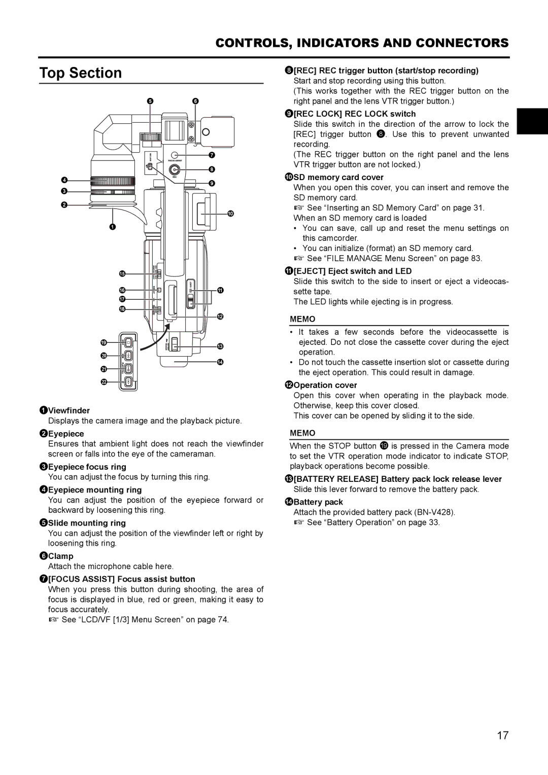
Top Section
8[REC] REC trigger button (start/stop recording) Start and stop recording using this button.
4
3
2
1
e
f g h
i
j
k
l
5 6
7
8
9
0
a |
b |
c |
d |
(This works together with the REC trigger button on the right panel and the lens VTR trigger button.)
9[REC LOCK] REC LOCK switch
Slide this switch in the direction of the arrow to lock the [REC] trigger button 8. Use this to prevent unwanted recording.
(The REC trigger button on the right panel and the lens VTR trigger button are not locked.)
0SD memory card cover
When you open this cover, you can insert and remove the SD memory card.
X See “Inserting an SD Memory Card” on page 31. When an SD memory card is loaded
•You can save, call up and reset the menu settings on this camcorder.
•You can initialize (format) an SD memory card.
X See “FILE MANAGE Menu Screen” on page 83.
a[EJECT] Eject switch and LED
Slide this switch to the side to insert or eject a videocas- sette tape.
The LED lights while ejecting is in progress.
MEMO
•It takes a few seconds before the videocassette is ejected. Do not close the cassette cover during the eject operation.
•Do not touch the cassette insertion slot or cassette during the eject operation. This could result in damage.
bOperation cover
1Viewfinder
Displays the camera image and the playback picture.
2Eyepiece
Ensures that ambient light does not reach the viewfinder screen or falls into the eye of the cameraman.
3Eyepiece focus ring
You can adjust the focus by turning this ring.
4Eyepiece mounting ring
You can adjust the position of the eyepiece forward or backward by loosening this ring.
5Slide mounting ring
You can adjust the position of the viewfinder left or right by loosening this ring.
6Clamp
Attach the microphone cable here.
7[FOCUS ASSIST] Focus assist button
When you press this button during shooting, the area of focus is displayed in blue, red or green, making it easy to focus accurately.
X See “LCD/VF [1/3] Menu Screen” on page 74.
Open this cover when operating in the playback mode. Otherwise, keep this cover closed.
This cover can be opened by sliding it to the side.
MEMO
When the STOP button i is pressed in the Camera mode to set the VTR operation mode indicator to indicate STOP, playback operations become possible.
c[BATTERY RELEASE] Battery pack lock release lever Slide this lever forward to remove the battery pack.
dBattery pack
Attach the provided battery pack
X See “Battery Operation” on page 33.
17