6![]()
![]()
![]()
![]()
![]()
![]()
![]()
![]()
![]()
![]()
![]()
![]()
![]()
![]()
![]()
![]()
![]()
![]()
![]()
![]()
![]()
![]()
![]()


 QU
QU
 ICK
ICK
 SET
SET U
U
 P
P
 GUIDE
GUIDE (cont.)


STEP
2
INSTALLATION
CONNECT VIDEO RECORDER TO TV
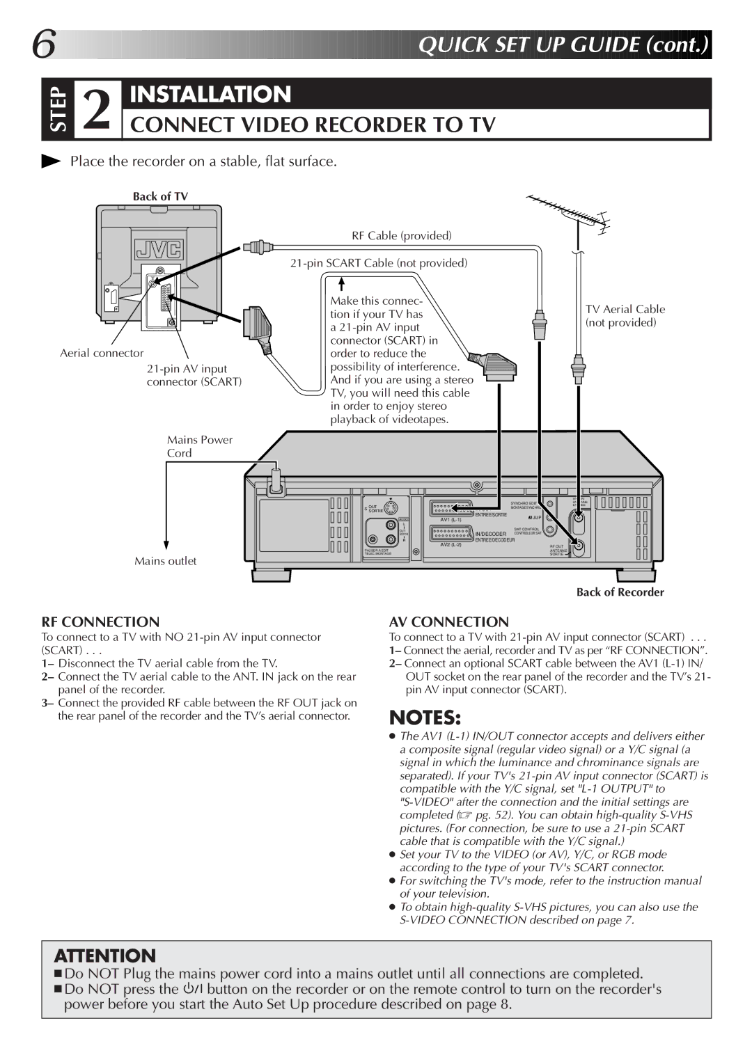
Place the recorder on a stable, flat surface.
Back of TV
Aerial connector
Mains Power
Cord
Mains outlet
RF Cable (provided)
Make this connec- tion if your TV has a
| OUT |
|
| SYNCHRO EDIT |
S |
| IN/OUT | MONTAGE SYNCHRO | |
SORTIE |
|
| ||
| AUDIO | AV1 | ENTREE/SORTIE | JLIP |
|
| |||
|
|
| ||
| OUT |
|
| SAT CONTROL |
| SORTIE |
| IN/DECODER CONTROLEUR SAT | |
ENTREE/DECODEUR
AV2
PAUSE/R.A.EDIT
TELEC./MONTAGE
TV Aerial Cable (not provided)
ANT. IN
ANTENNE
ENTREE
RF OUT
ANTENNE
SORTIE
Back of Recorder
RF CONNECTION
To connect to a TV with NO
1– Disconnect the TV aerial cable from the TV.
2– Connect the TV aerial cable to the ANT. IN jack on the rear panel of the recorder.
3– Connect the provided RF cable between the RF OUT jack on the rear panel of the recorder and the TV’s aerial connector.
AV CONNECTION
To connect to a TV with 21-pin AV input connector (SCART) . . .
1– Connect the aerial, recorder and TV as per “RF CONNECTION”. 2– Connect an optional SCART cable between the AV1
pin AV input connector (SCART).
NOTES:
●The AV1
●Set your TV to the VIDEO (or AV), Y/C, or RGB mode according to the type of your TV's SCART connector.
●For switching the TV's mode, refer to the instruction manual of your television.
●To obtain
ATTENTION
■Do NOT Plug the mains power cord into a mains outlet until all connections are completed.
■Do NOT press the ![]()
![]()
![]() button on the recorder or on the remote control to turn on the recorder's power before you start the Auto Set Up procedure described on page 8.
button on the recorder or on the remote control to turn on the recorder's power before you start the Auto Set Up procedure described on page 8.