RX-D701S
RX-D701S
Precautions
Features
Table of Contents
When operating a DVD player, set the mode selector o to DVD
Remote control
Front panel
How to open the front door
Rear panel
Display window
Before Installation
Putting batteries in the remote control
Checking the supplied accessories
FM antenna connection
Connecting the FM and AM antennas
Connecting the powered subwoofer
Connecting the speakers
Speaker Layout Diagram
Connecting the speakers
Connecting video components
Before connecting video components
Video conversion function
Video cable not supplied Composite video cable not supplied
Connecting a TV
Only for DVD recorder To S-video input
Connecting a DVD recorder or DVD player
When you enjoy sound recorded in DVD-Audio
With analog method
With digital method
‰ Ï Ì Ó
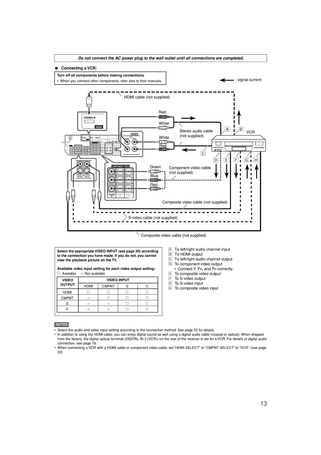
Connecting a VCR
Connecting a DBS tuner
How to open the front door
Connecting a video component to the AUX input jacks
Digital input terminals
Connecting the power cord
Digital audio connection
Turn off all components before making connections
For USB Terminal
USB connection
Now PC is ready for playback through the USB connection
How to install the USB drivers
USB drivers are installed automatically
Check if the drivers are correctly installed
Select the source to play
Turn on the power
To turn off the power into standby
Press STANDBY/ON or Audio on the remote control
Listening with headphones
Adjust the volume
Selecting the video input setting
Selecting the audio input setting
Turning off the sounds temporarily
Selecting the digital decode mode
From the remote control only Press Dimmer repeatedly
To restore the sound, press Muting again
Making sounds natural
Turning off the power with the Sleep Timer
Basic adjustment of auto memory
Signal and speaker indicators on the display
Press and hold Smart S. Setup until Setting UP flashes
Basic settings
When Silent appears twice in succession
When your clapping sound is detected successfully
When finishing displaying the setting values
When your clapping sound is not detected correctly
On the front panel
Basic setting items
From the remote control
Operation through on-screen display menus
Setup menu configuration
Before you start, remember
Menu operating procedure
Button indications on the screen
To select the desired submenu, press 5 or ∞ repeatedly
Press SET
Setting the items
Setting subwoofer information-SUBWOOFER
Initial setting Subwoofer no
Speaker distance
Setting the surround back speakers
Setting the speaker distance
Initial setting S Back OUT 2SPK
Setting subwoofer output-SUBWFR OUT
Setting the crossover frequency-CROSSOVER
Setting the low frequency effect attenuator
Initial setting Superimpose on
Initial setting ONE Touch OP OFF To recall the volume level
To cancel the One Touch Operation
Initial setting Cmpnt Select VCR
Basic adjustment items
Adjust Menu
Adjust
To start the adjustment, press
Press Test to check the speakers’ output balance
Adjusting the items
Reinforcing the bass-BASS Boost
Attenuating the input signal-INPUT ATT
Adjusting the virtual room size for DSP modes
Adjusting the effect level for DSP modes
Adjusting the center tone-CENTER Tone
Adjusting the liveness effect for DSP modes
Tuner operations are mainly done from the remote control
Tuning in to stations manually
Using preset tuning
To store the preset stations
To tune in a preset station
Selecting the FM reception mode
Dolby Surround
Reproducing theater ambience
Introducing the Surround modes
Dolby Digital
DTS
About other digital signals
Digital Acoustic Processor DAP modes
All Channel Stereo mode ALL CH Stereo
3D Headphone mode
Introducing the DSP modes
Virtual Surround Back
Using the Surround/DSP modes
DTSDolby Digital Incoming Signal Type
About the DSP modes
Selecting the Surround/DSP modes
When you select Auto Surround
From the remote control Select and play any source
Turn Multi JOG to select the Surround/DSP mode you want
Connections 1 AV Compu Link connection
Connections 2 Video cable connection
Case
One-touch video play
Connecting procedure
Automatic selection of TV’s input mode
Automatic power on/off
Turn on or off the VCR
Turn on or off the TV
Changing the remote control code for DVD recorder
DVD recorder or DVD player
Release DVR/DVD
Manufacturers’ codes for TV
Changing the transmittable signals for operating a TV
Release TV
Try to operate your TV by pressing TV
Manufacturers’ codes for VCR
Changing the transmittable signals for operating a VCR
Release VCR
Try to operate your VCR by pressing VCR
Try to operate your DVD player by pressing DVR/DVD
Release DBS/CATV
Manufacturers’ codes for Catv converter
Manufacturers’ codes for DBS tuner
Power
Troubleshooting
Remote control Tuner
General
Amplifier
FM tuner IHF
AM tuner
Audio Video Control Receiver
For Customer Use
RX-D702B
For Canada/pour le Canada
For Canada/pour le Canada
For U.S.A
Introduction
Table of Contents
AUDIO, TV/SIRIUS , DBS/CATV , VCR DVR/DVD
DVR/DVD, VCR, DBS, TV/SIRIUS, USB, FM/AM, AUX
DVR/DVD in Play
Display window
Getting started
Connecting the FM and AM antennas
Connecting the speakers
Connecting audio and video components
TV/SIRIUS
DVR/DVD
Vcrdbs
Stereo audio cable VCR Not supplied
Connecting a DBS tuner
Connecting a Sirius radio
Connecting the power cord
USB connection
How to install the USB drivers
Changing the source name
DVR/DVD VCR DBS TV SIRIUS* USB Wireless USB Terminal FM AM
Adjust the volume
Selecting the digital decode mode
Turning off the power with the Sleep Timer
Basic settings
If you change speaker distance manually
Basic setting items
Setup menu configuration
Menu operating procedure
Than 12 cm 4 3/4 inches
Back OUT
Setting
Audio Delay
Video Output
Sound adjustments
Setup menu configuration
Center Level
Adjusting the items
Adjusting the sound parameters for the Surround/DSP modes
Liveness
From the remote control only Press FM/AM to select the band
From the remote control Press FM/AM to select the band
FL CFR Slsr SBL SB SBR
DTS
Introducing the DSP modes
Using the Surround/DSP modes
Activating the Surround/DSP modes
RX-D702B Equipment To video input
Connecting procedure
Sirius radio
DVD recorder or DVD player
Release TV/SIRIUS
Try to operate your TV by pressing TV/SIRIUS
0, 100+ +10 Select the channel numbers
Change the channel numbers on
Enter recording pause. To start
Recording, press this button then
Release DBS/CATV
Sound and picture
Remote control Tuner
DVR/DVD, VCR, DBS, TV
Page
Page
RX-D702B
Audio / Video Control Receiver
Mises en garde, précautions et indications diverses
English
Table of Contents
Parts identification
SET / Tuner Preset
Display window
Getting started
AM antenna connection
Connecting the speakers
Connecting video components
Component Video
White
È Ô
White Stereo audio cable VCR
Component video cable not supplied
Red
Connecting a video component to the AUX input jacks
Connecting the power cord
USB connection
How to install the USB drivers
Basic operations
Adjust the volume
Selecting the digital decode mode
Turning off the power with the Sleep Timer
Basic settings
SBR SBL SL
Basic setting items
Setup menu configuration
To start the setting, press Setting
Press SET
Back OUT
Dual Mono
Audio Delay
Video Output
Sound adjustments
Setup menu configuration
Level 2 0
R SR SBR SBL SL
Adjusting the sound parameters for the Surround/DSP modes
Liveness
Tuner operations
Selecting the FM reception mode
Creating realistic sound fields
DTS
Introducing the DSP modes
Digital
Activating the Surround/DSP modes
AV Compu Link remote control system
Connecting procedure
Operating other JVC products
DVD recorder or DVD player
Operating other manufacturers’ products
English
Release DBS/CATV
Picture
Remote control Tuner
195 W/250 VA at operation
EN, FR
LVT1437-009A
RX-D702B
Introduction
Table of Contents
Parts identification
Front panel
Voltage Selector
220V 230 240V
Setting the voltage selector
220V 230 240V
Surround Back Speakers Surround Speakers
Connecting video components
White Stereo audio cable Not supplied
Connecting a DVD recorder or DVD player
È Ô
230 127V 240V
Hdmi cable not supplied
Connecting a video component to the AUX input jacks
Connecting the power cord
USB connection
How to install the USB drivers
Basic operations
Adjust the volume
Selecting the digital decode mode
Turning off the power with the Sleep Timer
Basic settings
SBR SBL SL
Basic setting items
Setup menu configuration
Menu operating procedure
Setting the items
Back OUT
Dual Mono
Audio Delay
Video Output
Sound adjustments
Setup menu configuration
Menu operating procedure
Adjusting the items
Adjusting the sound parameters for the Surround/DSP modes
Liveness
To change back to the 9 kHz interval
Setting the AM tuner interval spacing
On the front panel only
To select the 10 kHz interval
Selecting the FM reception mode
Creating realistic sound fields
DTS
Introducing the DSP modes
Using the Surround/DSP modes
Surround OFF Back to the beginning
220V 110V 230 127V 240V
Connecting procedure
Operating other JVC products
DVD recorder or DVD player
Operating other manufacturers’ products
Changing the transmittable signals for operating a VCR
Release DBS/CATV
Troubleshooting
Remote control Tuner
Total harmonic distortion IEC268-3/DIN
Control Receiver