RX-DP20VBK
LVT0965-001AJ
23.5 kg / 52.0 lb
For the main unit
Features Precautions
Introduction
Table of Contents
Display Window
Parts Identification
Front Panel
To open the front door
Dgtl Auto indicator
Dual indicator
Analog indicator
96/24 indicator
Rear Panel
Remote Control
Connecting the FM and AM Antennas
Before Installation
Checking the Supplied Accessories
Getting Started
AM Antenna Connections
Connecting the Speakers
Basic connecting procedure
Zone 1 speaker layout
Front speakers Center speaker Right / Left
Front speakers
Front speakers and center speaker
Enhance your audio system
Connecting a subwoofer
Powered
Left surround
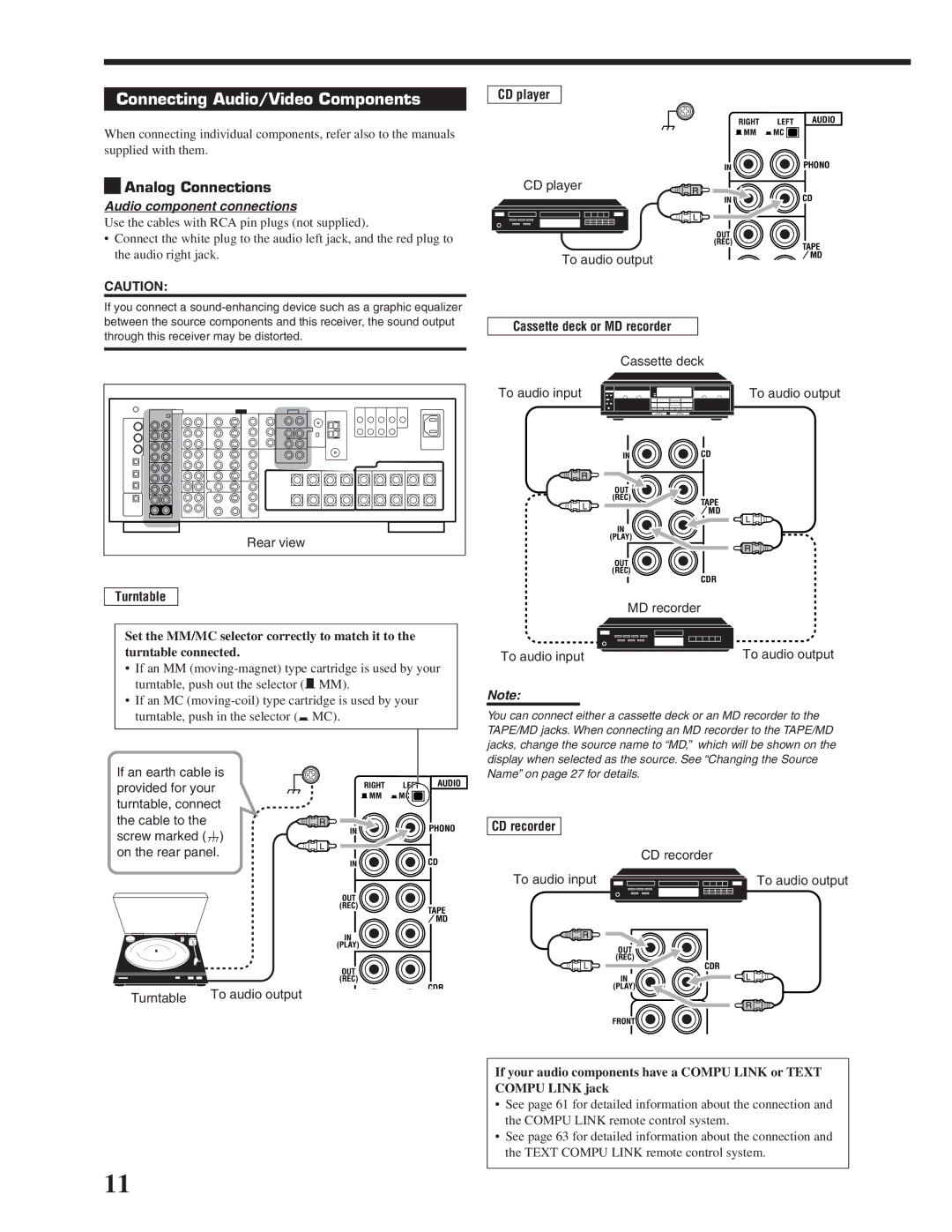
Connecting Audio/Video Components
Analog Connections
When using the digital input terminal
When attaching the front Terminal cover
When removing the cover
External 7.1-channel Output component Decoder Or DVD player
VCRs
VHS/S-VHS/VHS VCR
TV and/or DBS tuner
DBS tuner
DVD player
When you connect the DVD player with stereo output jacks
DVD player
Digital input terminals
Digital Connections
Digital output terminal
Setting Up the RF Rod Antenna
Using the RF Rod Antenna and IR Signal Transmitter
Find a place where you can attach the IR signal transmitter
Setting Up the IR Signal Transmitter
When using the remote control in the dark
Putting Batteries in the Remote Control
Connecting the Power Cord
Replace the cover
Required Connections for Zone
Power amplifier
Multi-Room Operations
Connection Å Connection ı
Basic Operating Procedure for Zone
Zone 2 ON/OFF lamp lights up
Turn Master Volume to
Press Zone 2 ON/OFF so that
Sound through the Zone 2 front Speakers
To turn off the power into standby mode
Turning the Power On and Off Standby
To turn on the power, press
Zone 1 Main Room Operations
Setting on
Canceling the Zone 1 Operations
Speaker and signal indicators on the display
Selecting the Zone 1 Source to Play
Adjusting the Zone 1 Volume
Selecting different sources for picture and sound
Mode
Selecting the Analog or Digital Input Mode
Activating the Zone 1 Front Speakers
Press and hold Input ATT inside
Attenuating the Input Signal
Indicator lights up on the display
Front door so that the Input ATT
Turning Analog Direct On and Off
Changing the Display Brightness
Making Sounds Natural
Changing the Source Name
Press Sleep repeatedly
Using the Sleep Timer
Basic adjustment auto memory
Recording a Source
Press Zone 2 Control inside
Last Zone Zone 2 volume Source appears Level appears
Zone 2 Sub-room Operations
Front door so that Zone Previously selected Zone
Zone 2 speakers, press Zone 2 ON/OFF so that
Canceling the Zone 2 Operations
To stop Zone 2 operations and sounds through
To use this receiver for Zone 2 operations
Selecting the Zone 2 Source to Play
Adjusting the Zone 2 Volume
Selected source name Zone 2 volume Level appears
DVD
Front speakers
Activating the Zone 2 Front Speakers
Press Zone 2 to activate the Zone
Muting the Zone 2 Sound
Receiving Radio Broadcasts
Tuning in to Stations Manually
Ex. When you press FM/AM With Zone 1/ZONE
Press FM/AM
Using Preset Tuning
Selecting the FM Reception Mode
Basic Settings
Setup Menu Configuration
Button To do
Operation through On-Screen Display Menus
Menu operation buttons
Press SET
Menu Operating Procedure
Press Setup Menu
YES
Setting the Speakers-SPEAKER Setting
Adjusting the Speaker Channel Output Levels-CHANNEL Level
1SPK
Front L Level
Auto
OFF
Front R Level
For each speaker
Setting the Speaker Distance
Setting the Bass Sounds-SUBWOOFER
LFE
Close
Setting the THX Audio-THX Audio Setup
Apart
Setting the Digital Input/Output Terminals
Setting the Surround Channel Output Speakers-SURR CH OUT
Setting the Audio Delay Level-AUDIO Delay
Selecting the Dual Mono Sound-DUAL Mono
Turning On and Off the Video Output
Setting the Video Input Terminals
Setting the Zone 2/Speakers 2 Usage -ZONE 2/SPEAKER
PCM
Showing the Text Information on the Display-FL Display
Memorizing the Volume Level for Each Source-ONE Touch OPE
Superimposing the Menus-SUPERIMPOSE
Text
Sound Adjustments
Adjustment Menu Configuration
Select a submenu on the Adjustment Menu
Adjust Menu
Display or erase the Adjustment Menu
Or an item on a submenu downwards or
To select the desired submenu
Press Adjust Menu
Press fi or % Down or UP repeatedly
Set other items on the same submenu if necessary
Bass
Adjustment procedure
Submenu items
MID
When one of the DSP modes except ALL CH Stereo is activated
Setting the Midnight Mode-MIDNIGHT Mode
Adjusting the Various Effects
Press Liveness repeatedly to adjust
When Dolby Pro Logic II Music is activated
When Neo6 Music is activated
Overall level of the effect 1 to
Introducing the Surround and THX Modes
Using the Surround and THX Modes
Reproducing Theater Ambience
DTS Digital Surround
Dolby Digital EX
Dolby Pro Logic
DTS Extended Surround DTS-ES
ES/EX/7.1 Available
Surround and THX Modes Applicable to the Various Software
Zone
Incoming Signal Type 2-channel Available Surround Mode
Available THX Mode
Activating the 7.1-channel reproduction
Activating the Surround and THX Modes
About Dialog Normalization
EXES7.1 on
Ex. When Dolby Digital is activated
Press Surround to activate the Surround Mode
To cancel the Surround mode
To adjust the speaker output level using the remote control
To cancel the THX and Surround modes
Press THX to activate the THX mode
To cancel the THX mode without canceling the Surround mode
3D Headphone Mode
Reproducing the Sound Field
Using the DSP Modes
Headphone Mode
Introducing the DSP Modes
Press Effect repeatedly to adjust the level
To adjust the DSP effects
To cancel the DSP modes
Activating the DSP Modes
Playback Modes
Using the Analog Multi-channel Playback Mode
Activating the Analog Multi-channel
MD recorder
Compu Link Remote Control System
Cassette deck
Supplied for this receiver, the receiver
At the same time
When you turn off the Zone 1 sound by pressing
When you turn off the Zone 2 source by pressing
Press the play 3 button on the CD player
Displaying the Disc Information on the TV screen
Text Compu Link Remote Control System
RX-DP20VBK
Disc Search Only for CD Player
To exit from the Disc information screen
Press Text Display while CD or MD is selected as the source
Disc Information screen
Zone 2 Learn
Press % / fi to move to Performer Then press SET
Press Text Display while CD is selected as the source
Press % / fi to move to SEARCH, then press
Press SET again
Press % / fi to move To the genre you
Press % / fi to move to SEARCH, then press SET
Press % / fi to move To GENRE, then Press SET
Press % / fi to move to Title INPUT, then press SET
Press Text Display while MD is selected as the source
Enter the disc title, referring to steps 3
Press % / fi to move to the genre you want, then press SET
Press % / fi to move to Title Input Then press SET
IR signal transmitter
AV Compu Link Remote Control System
Connections 1 IR Signal Transmitter Connection
Connections 2 AV Compu Link Connection
One-Touch Video Play
Connections 3 Video Cable Connection
Case
When you turn off the Zone 2 sound by pressing
Automatic Power On/Off Standby
Automatic Power On
One-Touch DVD Play
Tuner
Operating JVC’s Audio/Video Components
Operating Audio Components
Sound control section Amplifier
Turntable
CD player
CD player-changer
CD recorder
¶ REC
Operating Video Components
VCR VCR connected to the VCR 1 jacks
DVD player
Changing the Preset Signal Codes
Operating Other Manufacturers’ Equipment
Press VCR
Enter a manufacturer’s code using
Press and hold VCR
Buttons 1-9,
Release Audio on
Enter a manufacturer’s code using buttons 1-9,
Press and hold Audio Standby Press DVD
Release Audio Standby
Manufactures’ codes for VCR
Manufactures’ codes for DBS tuner Manufacturer Codes
Manufactures’ codes for Catv converter Manufacturer Codes
Manufacturer Codes
Set the LEARN/TRANSMIT
Storing the Remote Signals Manually
To store the signals
Zone 1/ZONE 2 selector to
Control
For the Zone 1 operations For the Zone 2 operations
Press the desired button
To use the stored signals
To erase the stored signals
\and
Multi-room operations Zone1/Zone
Troubleshooting
Problem Possible Cause Solution
Surround/THX
General
CATV/DBS
FM/AM
Amplifier
Specifications
Output Power
Audio
AM tuner
Video
FM tuner IHF
General
Limited Warranty
Authorized Service Centers
RX-DP20VBK


 Analog Connections