3 CONNECTIONS (contd.)
3-3 Connecting signal input/output terminals
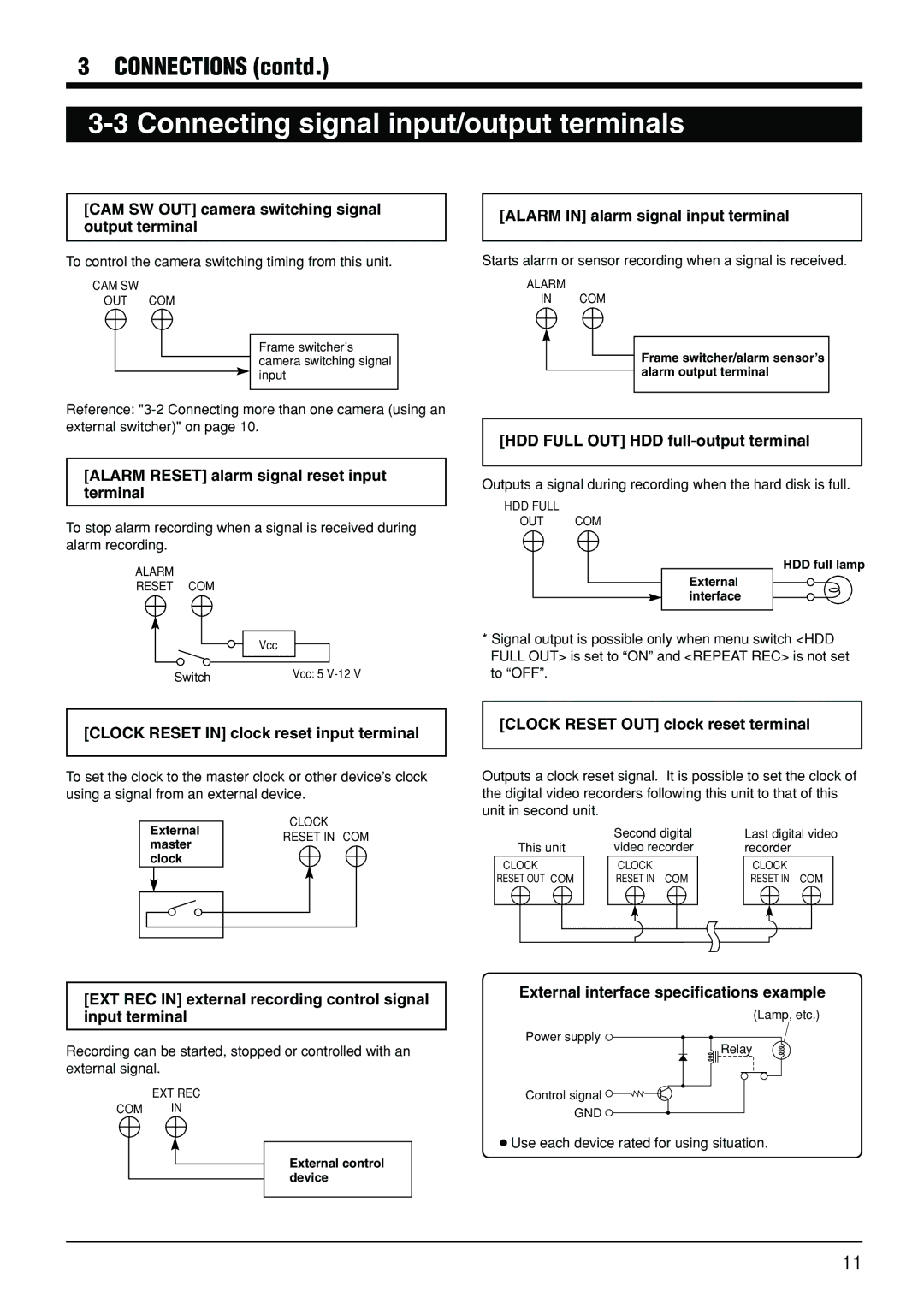
[CAM SW OUT] camera switching signal output terminal
To control the camera switching timing from this unit.
CAM SW
OUT COM
Frame switcher’s camera switching signal input
Reference:
[ALARM RESET] alarm signal reset input terminal
To stop alarm recording when a signal is received during alarm recording.
ALARM
RESET COM
Vcc
Switch | Vcc: 5 |
[ALARM IN] alarm signal input terminal
Starts alarm or sensor recording when a signal is received.
ALARM
IN COM
Frame switcher/alarm sensor’s alarm output terminal
[HDD FULL OUT] HDD full-output terminal
Outputs a signal during recording when the hard disk is full.
HDD FULL
OUT COM
HDD full lamp
External interface
*Signal output is possible only when menu switch <HDD FULL OUT> is set to “ON” and <REPEAT REC> is not set to “OFF”.
[CLOCK RESET IN] clock reset input terminal
To set the clock to the master clock or other device’s clock using a signal from an external device.
CLOCK
ExternalRESET IN COM master
clock
[CLOCK RESET OUT] clock reset terminal
Outputs a clock reset signal. It is possible to set the clock of the digital video recorders following this unit to that of this unit in second unit.
|
|
| Second digital | Last digital video | |||
This unit | video recorder | recorder | |||||
CLOCK |
| CLOCK |
| CLOCK |
| ||
RESET OUT COM |
| RESET IN COM |
| RESET IN COM |
| ||
|
|
|
|
|
|
|
|
|
|
|
|
|
|
|
|
[EXT REC IN] external recording control signal input terminal
Recording can be started, stopped or controlled with an external signal.
EXT REC
COM IN
External control device
External interface specifications example
(Lamp, etc.)
Power supply ![]()
Relay
Control signal ![]()
![]()
![]()
GND ![]()
●Use each device rated for using situation.
11