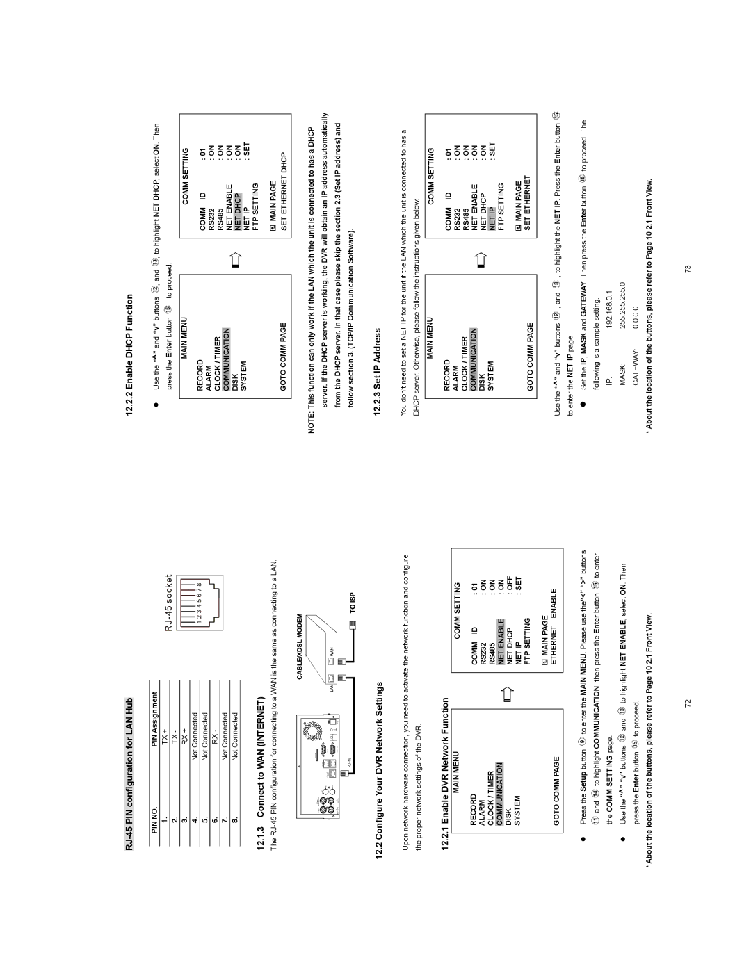
RJ-45 PIN configuration for LAN Hub
PIN NO. | PIN Assignment |
1. | TX + |
12.2.2 Enable DHCP Function
z Use the “^” and “v” buttons ![]() , and
, and ![]() , to highlight NET DHCP; select ON. Then
, to highlight NET DHCP; select ON. Then
|
|
| |||||||||||
2. | TX - | ||||||||||||
|
|
|
|
|
|
|
|
|
|
|
|
|
|
3. | RX + |
|
|
|
|
|
|
|
|
|
|
|
|
4. | Not Connected |
|
|
|
|
|
|
|
|
|
|
|
|
|
| 1 2 3 4 5 6 7 8 |
| ||||||||||
5. | Not Connected |
|
|
| |||||||||
|
|
|
|
|
|
|
|
|
|
|
| ||
6. | RX - |
|
|
|
|
|
|
|
|
|
|
|
|
7. | Not Connected |
|
|
|
|
|
|
|
|
|
|
|
|
|
|
|
|
|
|
|
|
|
|
|
| ||
8. | Not Connected |
|
|
|
|
|
|
|
|
|
|
|
|
12.1.3Connect to WAN (INTERNET)
The
press the Enter button | to proceed. |
MAIN MENU
RECORD
ALARM
CLOCK / TIMER
COMMUNICATION
DISK
SYSTEM
GOTO COMM PAGE
COMM SETTING
COMM ID | : 01 | |
RS232 | : ON | |
RS485 | : ON | |
NET ENABLE | : ON | |
|
| : ON |
NET DHCP | ||
NET IP |
| : SET |
FTP SETTING |
| |
![]() MAIN PAGE
MAIN PAGE
SET ETHERNET DHCP
12.2 Configure Your DVR Network Settings
Upon network hardware connection, you need to activate the network function and configure the proper network settings of the DVR.
NOTE: This function can only work if the LAN which the unit is connected to has a DHCP server. If the DHCP server is working, the DVR will obtain an IP address automatically from the DHCP server. In that case please skip the section 2.3 (Set IP address) and follow section 3. (TCP/IP Communication Software).
12.2.3 Set IP Address
You don’t need to set a NET IP for the unit if the LAN which the unit is connected to has a DHCP server. Otherwise, please follow the instructions given below:
MAIN MENU
COMM SETTING
12.2.1 Enable DVR Network Function
MAIN MENU
RECORD
ALARM
CLOCK / TIMER
COMMUNICATION
DISK
SYSTEM
COMM SETTING
COMM ID | : 01 | |
RS232 | : ON | |
RS485 | : ON | |
NET ENABLE |
| : ON |
NET DHCP |
| : OFF |
NET IP | : SET | |
FTP SETTING |
| |
RECORD
ALARM CLOCK / TIMER COMMUNICATION DISK
SYSTEM
GOTO COMM PAGE
COMM ID | : 01 | |
RS232 | : ON | |
RS485 | : ON | |
NET ENABLE | : ON | |
NET DHCP | : ON | |
|
| : SET |
NET IP | SETTING | |
FTP |
| |
MAIN PAGE |
| |
SET ETHERNET |
| |
GOTO COMM PAGE
![]() MAIN PAGE ETHERNET ENABLE
MAIN PAGE ETHERNET ENABLE
Use the “^” and “v” buttons ![]() , and
, and ![]() , to highlight the NET IP. Press the Enter button
, to highlight the NET IP. Press the Enter button ![]() to enter the NET IP page
to enter the NET IP page
zPress the Setup button ![]() to enter the MAIN MENU. Please use the“<” “>” buttons
to enter the MAIN MENU. Please use the“<” “>” buttons
![]() and
and ![]() to highlight COMMUNICATION; then press the Enter button
to highlight COMMUNICATION; then press the Enter button ![]() to enter the COMM SETTING page.
to enter the COMM SETTING page.
zUse the “^” “v” buttons ![]() and
and ![]() to highlight NET ENABLE; select ON. Then
to highlight NET ENABLE; select ON. Then
press the Enter button ![]() to proceed.
to proceed.
*About the location of the buttons, please refer to Page 10 2.1 Front View.
zSet the IP, MASK and GATEWAY. Then press the Enter button ![]() to proceed. The following is a sample setting.
to proceed. The following is a sample setting.
IP:192.168.0.1
MASK: 255.255.255.0
GATEWAY: 0.0.0.0
* About the location of the buttons, please refer to Page 10 2.1 Front View.
72 | 73 |