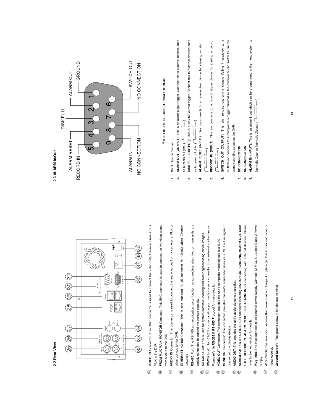
2.2 Rear View
2.3 ALARM In/Out
DISK FULL
25 | 26 | 27 | 28 | 29 | 30 | 31 |
| |
|
|
|
|
| SD Card |
|
|
|
| FROM MUX |
|
|
|
|
|
|
|
VIDEO | MAIN MONITOR |
|
|
|
|
|
|
|
|
| AUDIO |
|
|
|
|
| |
IN |
| IN |
|
|
|
|
| |
|
|
| ETHERNET |
|
|
|
| |
|
|
| 10/100 |
|
|
|
| |
|
|
|
|
|
|
|
| |
OUT |
| OUT |
|
|
|
|
| |
|
|
|
|
|
|
| ||
TO | TO |
|
|
| ALARM | I/O | DC12V | |
MUX'S VCR IN | MONITOR |
|
|
| ||||
|
|
|
|
|
| |||
32 | 33 | 34 | 35 | 37 | 38 36 |
VIDEO IN Connector: This BNC connector is used to connect the video output from a camera or a MUX to the DVR.
ALARM RESET |
|
RECORD IN |
|
5 | 4 |
9 8
ALARM IN |
NO CONNECTION |
|
| ALARM OUT |
|
| GROUND |
3 | 2 | 1 |
7 6
SWITCH OUT
NO CONNECTION
FROM MUX MAIN MONITOR Connector: This BNC connector is used to connect the live video output from a MUX to the DVR.
AUDIO IN Connector: This connector is used to connect the audio output from a camera, a MUX or other devices to the DVR.
ETHERNET 10/100 Connector: This is one standard
SD CARD Slot: This is used for system software updating and archiving/accessing critical images.
VIDEO OUT Connector: The connector provides the unit’s composite video signals to a MUX.
MONITOR Connector: The connector provides the unit’s composite video or a MUX’s live signal if connected to a display device.
AUDIO OUT: This provides the unit’s audio signal to a speaker.
ALARM I/O: This is a
Plug Inlet: The inlet connects to an external power supply. Connect 12 V DC UL Listed Class 2 Power Supply.
Wire Catch: The wire catch secures the power cord and keeps it in place (so that it does not droop or hang loosely).
Ground Screw’s: The ground screw is for chassis terminal.
ʽTHIS FIGURE IS LOOKED FROM THE REAR
1.GND: Ground Contact.
2.ALARM OUT (OUTPUT): This is an alarm output trigger. Connect this to external devices such
|
|
| 5V |
|
as buzzers or lights. ( |
| 0V(Active) | ) | |
| ||||
3.DISK FULL (OUTPUT): This is a disk full output trigger. Connect this to external devices such
|
|
| 5V |
|
as buzzers or lights. ( |
| 0V(Active) | ) | |
| ||||
4.ALARM RESET (INPUT): This pin connects to an
( |
|
| 5V | ) |
|
| 0V(Active) | ||
|
5. RECORD IN (INPUT): This pin connects to a record trigger device for starting a record.
( |
|
| 5V | ) |
|
| 0V(Active) | ||
|
6.SWITCH OUT (OUTPUT): This pin, sending out timing signals (falling / negative) to a multiplexer, connects to a multiplexer’s trigger terminal so the multiplexer can switch to use the same recording speed as the DVR.
7.NO CONNECTION
8.NO CONNECTION
9.ALARM IN (INPUT): This is an alarm input which can be programmed in the menu system to
Normally Open or Normally Closed. ( |
|
| 5V | ) |
|
| 0V(Active) | ||
|
|
12 | 13 |