Manuals
/
K-Tec
/
Home Audio
/
Satellite Radio
K-Tec
manual
MT2000-0200-1 Rev f 10-2007 DCN0160
Models:
MT2000
1
33
35
35
Download
35 pages
34.98 Kb
28
29
30
31
32
33
34
35
Page 33
Image 33
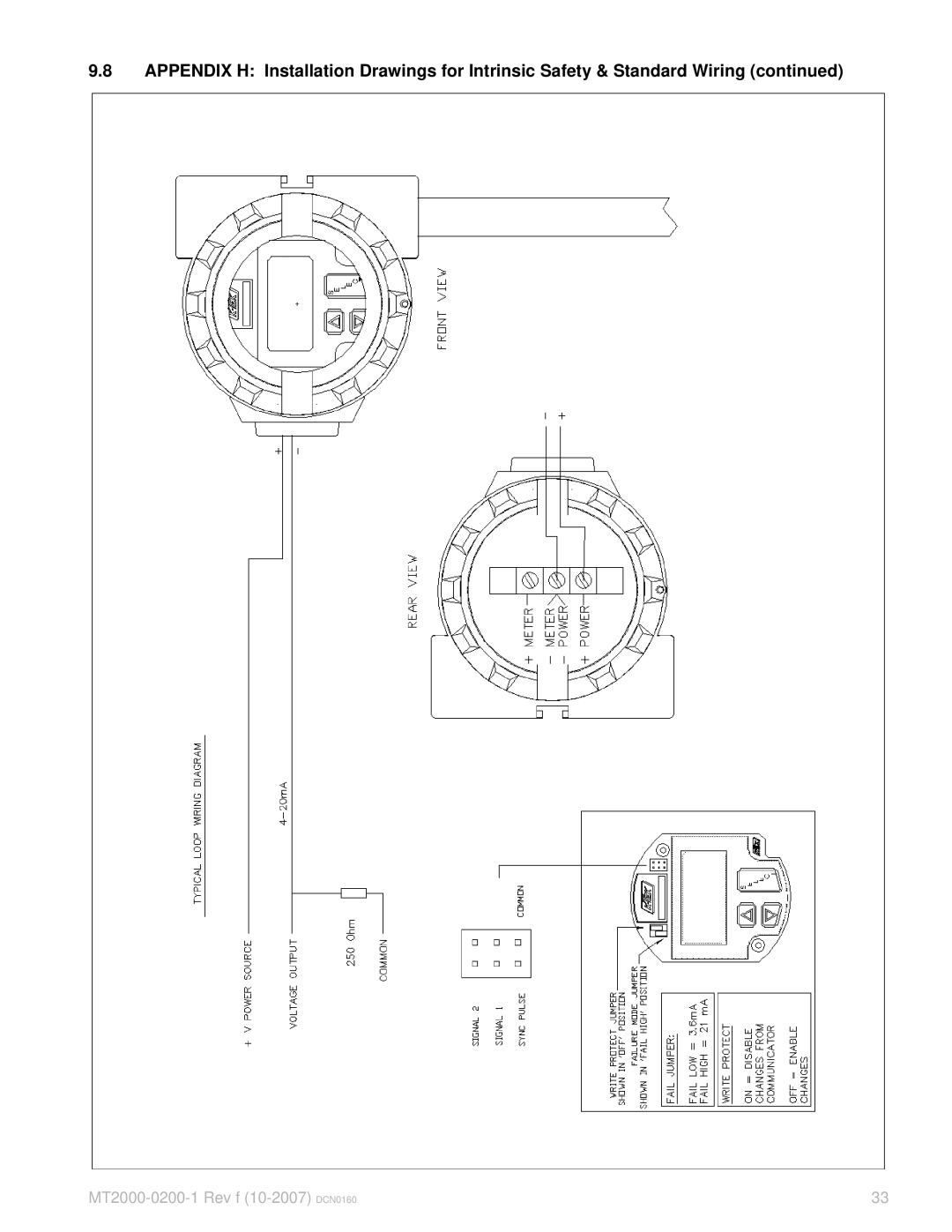
9.8
APPENDIX H: Installation Drawings for Intrinsic Safety & Standard Wiring (continued)
MT2000-0200-1
Rev f
(10-2007)
DCN0160
33
Page 32
Page 34
Page 33
Image 33
Page 32
Page 34
Contents
Guided Wave Radar Level Transmitter
Table of Contents
Appendices
List of Figures
Introduction
Overview
Ambient Temperature
Storage Information
Measurement cycle consists of the following
Ultra Low Dielectric ULD Measure Method
Direct Reflect Mode standard cont’d
Mounting Requirements
Installation
Shortening of Probe
Factory Default Configuration
MT2000 Guided Wave Radar Guidelines
URV = Probe Length LRV = 0 in. / 0 mm
Quickstart Procedure
Wiring
Commissioning
MT2000 Guided Wave Radar Guidelines cont’d
Quickstart Procedure cont’d
Verify Proper Power-Up
Setting the 4mA and 20 mA Points Using the Pushbutton Menu
Calibration Menu
LCD Menu Operation
Threshold Level Parameter THV and Gain Setting GS
Detailed Configuration Parameters Direct Mode Blanking Menu
Threshold Level Parameter THV and Gain Setting GS cont’d
Advanced Parameter Settings
L1O
KO & KG
Advanced Parameter Settings cont’d
Ultra Low Dielectric ULD Mode Configuration
= H * Sqrt DC H + L
DC = I + H L / H2
Advanced Output Configuration
Ultra Low Dielectric ULD Mode Configuration cont’d
Setting the DAC trim
DAC TrimFigure
Bench Calibration of the 4mA & 20mA Points
6 4mA & 20mA Calibration Using Actual Level Input
Jumper Switch Settings
Reversing The Output Action Using Actual Level Input
Troubleshooting Information
Possible Symptoms
Valid Current Loop Outputs
Electronics Module Replacement
Possible Symptoms cont’d
Honeywell DE Output Option
Interoperability and Conformance Class
Operating Modes
Hart Protocol Interface Option
Hart Communicator
Compatibility
LRV
Glossary of Terms
Appendix a Sensor Trim
Appendices
END CFG Menu
Configuration 2 Hidden Menu
TMP
Setting up Linearization Table Points
To access the linearization table
Appendix C Linearization
To clear the linearization table
MT2000 Interface
Appendix D Interface Applications
Scope Settings Channel a
Use and setup of the oscilloscope for the MT2000
Prerequisites
Channel B
Appendix F CE Certificate of Conformity
Appendix G Exida Certificate
MT2000-0200-1 Rev f 10-2007 DCN0160
MT2000-0200-01 Rev f 10-2007 DCN0160
MT2000-0200-1 Rev f 10-2007 DCN0160
3a, 3b
Appendix I Mounting Configurations
10a
10b
Year Warranty for
Appendix J Warranty Statement
Top
Page
Image
Contents