4.4.4Ultra Low Dielectric (ULD) Mode Configuration (cont’d)
If it is not practical to establish a known level in the vessel before commissioning the MT2000 a demo MT2000 with a short probe can be used in a small container of the product to estimate the product dielectric constant with this procedure. If this estimated DC is used, we recommend verifying it later with a known vessel level that is as high as possible.
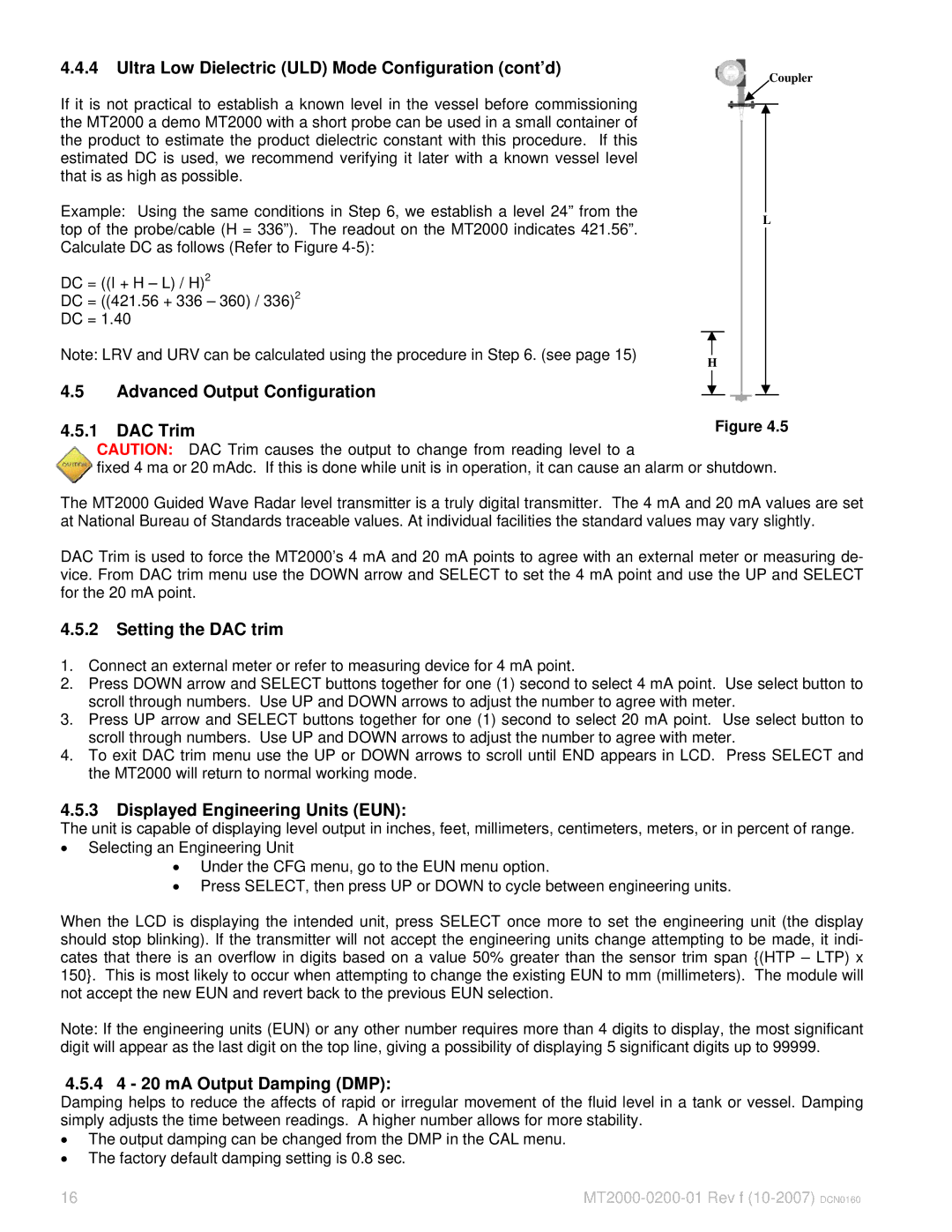
Example: Using the same conditions in Step 6, we establish a level 24” from the top of the probe/cable (H = 336”). The readout on the MT2000 indicates 421.56”. Calculate DC as follows (Refer to Figure
DC = ((I + H – L) / H)2
DC = ((421.56 + 336 – 360) / 336)2
DC = 1.40
Note: LRV and URV can be calculated using the procedure in Step 6. (see page 15) | H |
|
4.5Advanced Output Configuration
Coupler
L
4.5.1 DAC TrimFigure 4.5
CAUTION: DAC Trim causes the output to change from reading level to a
fixed 4 ma or 20 mAdc. If this is done while unit is in operation, it can cause an alarm or shutdown.
The MT2000 Guided Wave Radar level transmitter is a truly digital transmitter. The 4 mA and 20 mA values are set at National Bureau of Standards traceable values. At individual facilities the standard values may vary slightly.
DAC Trim is used to force the MT2000’s 4 mA and 20 mA points to agree with an external meter or measuring de- vice. From DAC trim menu use the DOWN arrow and SELECT to set the 4 mA point and use the UP and SELECT for the 20 mA point.
4.5.2Setting the DAC trim
1.Connect an external meter or refer to measuring device for 4 mA point.
2.Press DOWN arrow and SELECT buttons together for one (1) second to select 4 mA point. Use select button to scroll through numbers. Use UP and DOWN arrows to adjust the number to agree with meter.
3.Press UP arrow and SELECT buttons together for one (1) second to select 20 mA point. Use select button to scroll through numbers. Use UP and DOWN arrows to adjust the number to agree with meter.
4.To exit DAC trim menu use the UP or DOWN arrows to scroll until END appears in LCD. Press SELECT and the MT2000 will return to normal working mode.
4.5.3Displayed Engineering Units (EUN):
The unit is capable of displaying level output in inches, feet, millimeters, centimeters, meters, or in percent of range.
•Selecting an Engineering Unit
•Under the CFG menu, go to the EUN menu option.
•Press SELECT, then press UP or DOWN to cycle between engineering units.
When the LCD is displaying the intended unit, press SELECT once more to set the engineering unit (the display should stop blinking). If the transmitter will not accept the engineering units change attempting to be made, it indi- cates that there is an overflow in digits based on a value 50% greater than the sensor trim span {(HTP – LTP) x 150}. This is most likely to occur when attempting to change the existing EUN to mm (millimeters). The module will not accept the new EUN and revert back to the previous EUN selection.
Note: If the engineering units (EUN) or any other number requires more than 4 digits to display, the most significant digit will appear as the last digit on the top line, giving a possibility of displaying 5 significant digits up to 99999.
4.5.4 4 - 20 mA Output Damping (DMP):
Damping helps to reduce the affects of rapid or irregular movement of the fluid level in a tank or vessel. Damping simply adjusts the time between readings. A higher number allows for more stability.
•The output damping can be changed from the DMP in the CAL menu.
•The factory default damping setting is 0.8 sec.
16 |