9.4 APPENDIX D: Interface Applications | MT2000 Interface | |
|
| |
It is possible to use an MT2000 to determine the level of an interface but certain require- |
| |
ments must be met: |
| |
1. | The dielectric constant of the upper liquid must be low (between 2 and 3). |
|
2. | The dielectric constant of the lower liquid must be higher than the upper liquid (10 or |
|
| greater). | A |
3. | The interface layer must be contained within a few inches. |
|
4. | A means of venting all vapor/gas from the top of the chamber must be available. |
|
5.The standard MT2000 can only measure the interface of two liquids in a completely flooded chamber. For interface measurements with vapor space above the upper fluid, the MT2000 interface option must be used. Refer to the MT2000 Total and Interface
Level Transmitter Data Sheet on the
ML OIL
CAUTION:
1.If the dielectric constant of the upper phase varies it will have an impact on the accuracy of the measurement. Should it change significantly it can be necessary
| to |
|
2. | If the chamber does not remain totally flooded the interface measurement will not | Wa- |
| ||
| be correct. |
|
3. | A means of venting all vapor/gas must be incorporated. This is typically accom- | Figure 9.3 |
| plished by installing a “bleed ring” between the top flange on the chamber and |
the MT2000.
4.A means of moving the interface between two known points is extremely beneficial, and is generally ac- complished using “drain rings” at the upper and lower process connections. This will allow setting 0% and 100% interface levels at the transmitter to make calibration (and resetting sensor trim if needed) much more accurate.
5.The MT2000 can only measure the interface between two liquids be operated in a chamber or vessel that MUST remains completely flooded. If this condition is not met, the measurement will be invalid. If the installation will have a vapor space continuously present in top of the chamber the M4AI module (MT2000 interface module) must be used. Refer to the MT2000 Total and Interface Level Transmitter Data Sheet on the
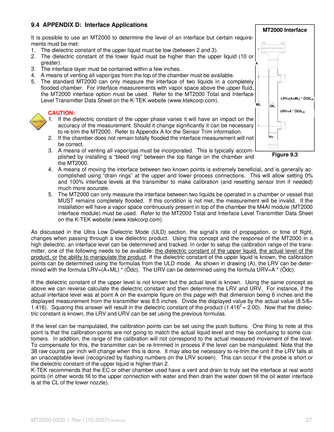
As discussed in the Ultra Low Dielectric Mode (ULD) section, the signal’s rate of propagation, or time of flight, changes when passing through a low dielectric product. Using this concept and the response of the MT2000 in a high dielectric, an interface level can be determined and tracked. In order to setup the calibration range of the trans- mitter, one of the following needs to be available: the dielectric constant of the upper liquid, the actual level of the product, or the ability to manipulate the product. If the dielectric constant of the upper liquid is known, the calibration points can be determined using the formulas from the ULD mode. As shown in drawing (A), the LRV can be deter- mined with the formula LRV=(A+ML) * (Ödc). The URV can be determined using the formula URV=A * (Ödc).
If the dielectric constant of the upper level is not known but the actual level is known. Using the same concept as above we can reverse calculate the dielectric constant and then determine the LRV and URV. For instance, if the actual interface level was at point A on the example figure on this page with that dimension being 6 inches and the displayed measurement from the transmitter was 8.5 inches. Divide the displayed value by the actual value (8.5/6= 1.416). Squaring this answer will result in the dielectric constant of the product (1.4162 = 2.00). Now that the dielec- tric constant is known, the LRV and URV can be set using the previous formulas.
If the level can be manipulated, the calibration points can be set using the push buttons. One thing to note at this point is that the calibration points are not going to match the actual liquid level and may be confusing to some cus- tomers. In addition, the range of the calibration will not correspond to the actual measured movement of the level. To compensate for this, the transmitter can be
27 |
