2.3.1Direct Reflect Mode (standard) (cont’d)
The measurement principle using TDR is based on the fact that a dielectric constant discontinuity or geometric change will yield a negative pulse having certain amplitude below the baseline. The greater the dielectric constant difference, the greater the negative amplitude of the return signal. This means that a signal will show up on the baseline if there is a substantial change from a nozzle diameter to an open tank, for example, as signal plot at the process connection. This fact needs to be taken into account in order to configure the MT2000 properly (Consult section on commissioning).
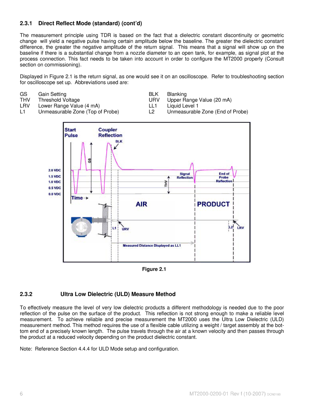
Displayed in Figure 2.1 is the return signal, as one would see it on an oscilloscope. Refer to troubleshooting section for oscilloscope set up. Abbreviations used are:
GS | Gain Setting | BLK | Blanking |
THV | Threshold Voltage | URV | Upper Range Value (20 mA) |
LRV | Lower Range Value (4 mA) | LL1 | Liquid Level 1 |
L1 | Unmeasurable Zone (Top of Probe) | L2 | Unmeasurable Zone (End of Probe) |
Figure 2.1
2.3.2Ultra Low Dielectric (ULD) Measure Method
To effectively measure the level of very low dielectric products a different methodology is needed due to the poor reflection of the pulse on the surface of the product. This reflection is not strong enough to make a reliable level measurement. To achieve reliable and precise measurement the MT2000 uses the Ultra Low Dielectric (ULD) measurement method. This method requires the use of a flexible cable utilizing a weight / target assembly at the bot- tom end of a precisely known length. The pulse travels through the air at a known velocity and then passes through the product at a reduced velocity depending on the product dielectric constant.
Note: Reference Section 4.4.4 for ULD Mode setup and configuration.
6 |