9.5APPENDIX E: Oscilloscope Use & Setup for Troubleshooting
9.5.1General Setup
•Connect Channel A to Pin 6
•Connect GND to Pin 3
•Connect Trigger to External to Pin 4
•Set Volts to 500 mV / div
•Set Time to 50 ųSec / div
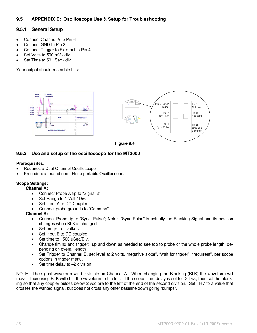
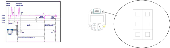
Your output should resemble this:
Pin 6 Return
Signal
Pin 5
Not used
Pin 4
Sync Pulse
Pin 1 Not used
Pin 2 Not used
Pin 3 Ground or Common
Figure 9.4
9.5.2Use and setup of the oscilloscope for the MT2000
Prerequisites:
•Requires a Dual Channel Oscilloscope
•Procedure is based upon Fluke portable Oscilloscopes
Scope Settings:
Channel A:
•Connect Probe A tip to “Signal 2”
•Set Range to 1 Volt / Div.
•Set input A to DC Coupled
•Connect probe grounds to “Common”
Channel B:
•Connect Probe tip to “Sync. Pulse”; Note: “Sync Pulse” is actually the Blanking Signal and its position changes when BLK is changed.
•Set range to 1 volt/div
•Set input B to DC coupled
•Set time to ~500 uSec/Div.
•Change timing and trigger: up and down as needed to see top fo probe or the whole probe length, de- pending on overall length
•Set Trigger to Channel B, set level at 2 volts, “negative slope”, “wait for trigger”, “recurrent”, per scope options in trigger menu.
•Set time delay to
NOTE: The signal waveform will be visible on Channel A. When changing the Blanking (BLK) the waveform will move. Increasing BLK will shift the waveform to the left. If the scope time delay is set to
28 |