4.1Quickstart Procedure (cont’d)
|
|
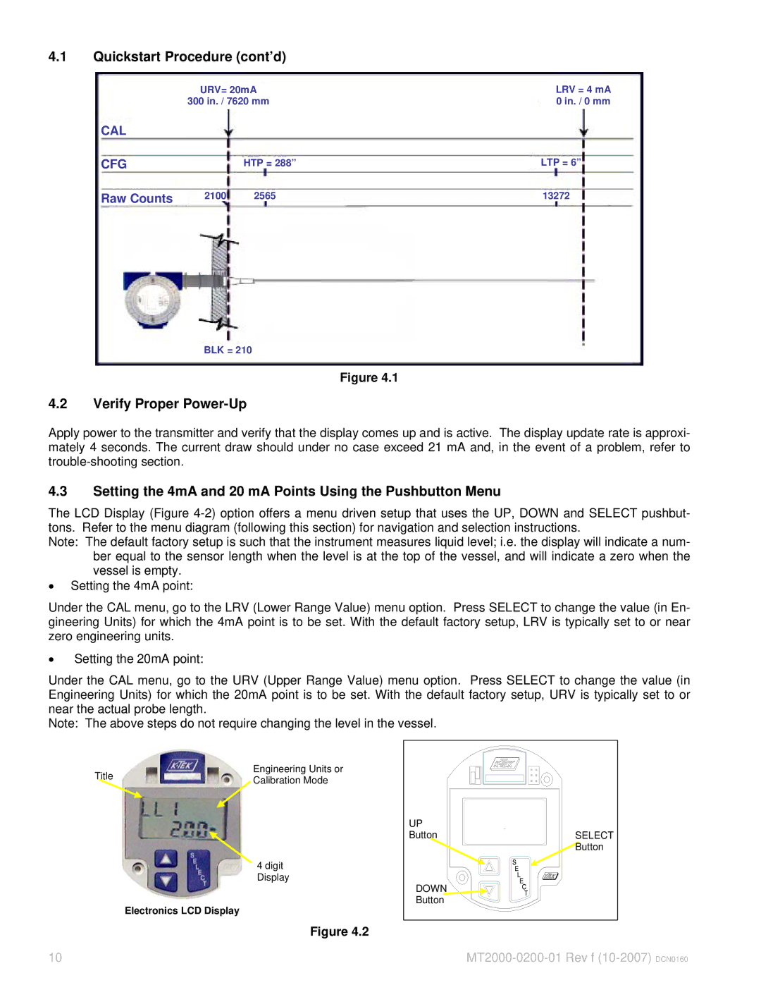
| URV= 20mA |
|
|
|
|
| LRV = 4 mA | |||||
| 300 in. / 7620 mm |
|
|
|
|
| 0 in. / 0 mm | |||||||
|
|
|
|
|
|
|
|
|
|
|
|
|
|
|
CAL |
|
|
|
|
|
|
|
|
|
|
|
|
|
|
|
|
|
|
|
|
|
|
|
|
|
|
|
|
|
|
|
|
|
|
|
|
|
|
| LTP = 6” | ||||
CFG |
|
|
|
|
| HTP = 288” |
|
|
| |||||
|
|
|
|
|
|
|
|
|
|
|
| |||
|
|
|
|
|
|
|
|
|
|
|
|
|
|
|
| 2100 | 2565 |
|
| 13272 |
|
| |||||||
Raw Counts |
|
|
|
|
|
|
|
|
| |||||
|
|
|
|
|
| |||||||||
|
|
| ||||||||||||
BLK = 210
Figure 4.1
4.2Verify Proper Power-Up
Apply power to the transmitter and verify that the display comes up and is active. The display update rate is approxi- mately 4 seconds. The current draw should under no case exceed 21 mA and, in the event of a problem, refer to
4.3Setting the 4mA and 20 mA Points Using the Pushbutton Menu
The LCD Display (Figure
Note: The default factory setup is such that the instrument measures liquid level; i.e. the display will indicate a num- ber equal to the sensor length when the level is at the top of the vessel, and will indicate a zero when the vessel is empty.
•Setting the 4mA point:
Under the CAL menu, go to the LRV (Lower Range Value) menu option. Press SELECT to change the value (in En- gineering Units) for which the 4mA point is to be set. With the default factory setup, LRV is typically set to or near zero engineering units.
•Setting the 20mA point:
Under the CAL menu, go to the URV (Upper Range Value) menu option. Press SELECT to change the value (in Engineering Units) for which the 20mA point is to be set. With the default factory setup, URV is typically set to or near the actual probe length.
Note: The above steps do not require changing the level in the vessel.
Title | Engineering Units or | |
Calibration Mode | ||
|
4 digit Display
Electronics LCD Display
Figure 4.2
10
UP |
|
Button | SELECT |
| Button |
DOWN |
|
Button |
|