TS-2000 TS-2000X TS-B2000
Features
Supplied Accessories
Thank YOU
Thank YOU
Models Covered by this Manual
Market Codes
TypeThe Americas
Type Europe E2-type Spain
Precautions
Contents
Contents
Scan
Operator Conveniences
Installing Options
Maintenance
Optional Accessories
Specifications
Installation
Antenna Connection
Ground Connection
Lightning Protection
Replacing Fuses
DC Power Supply Connection
Installation
Rear Panel
Accessory Connections
Front Panel
Your First QSO HF/ 50 MHz band
Press + or -to select an HF/ 50 MHz Amateur radio band
Transmitting
Your First QSO VHF/ UHF band
Your First QSO VHF/ UHF band
Getting Acquainted
Front Panel
Getting Acquainted
@5Tuning control
9LSB/ USB/ Auto key
@0CW/ FSK/ REV key
@1FM/ AM/ NAR key
$3TNC Status Indicators
#4QUICK Memo keys
MR key
Key
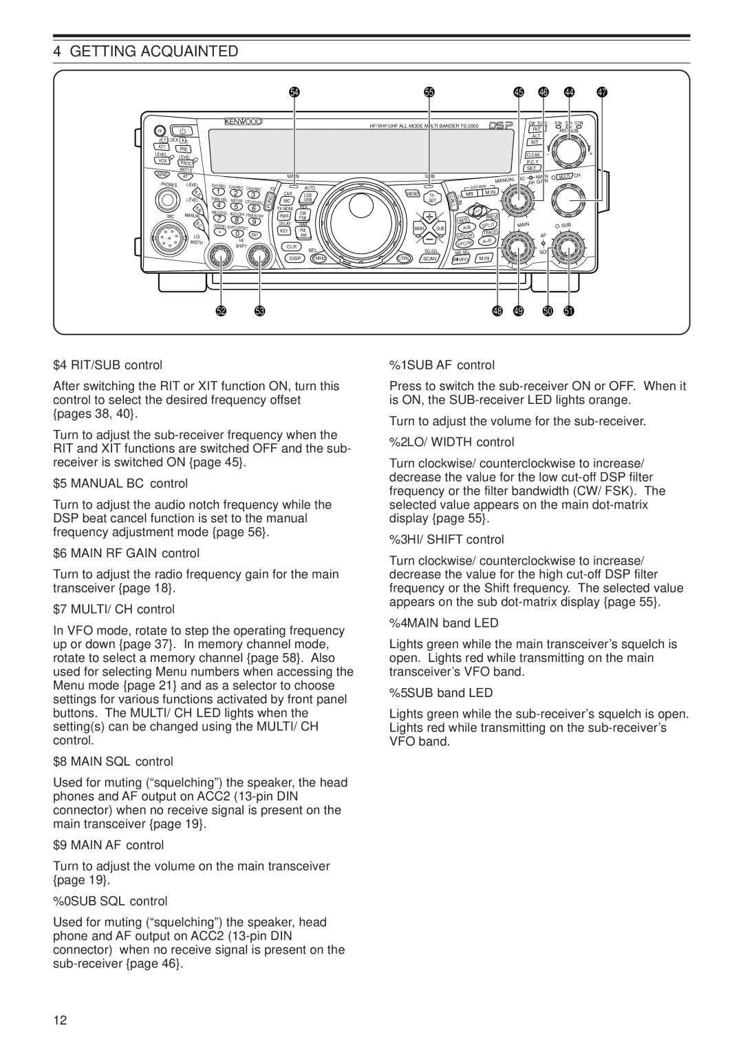
$4RIT/SUB control
$5MANUAL BC control
$6MAIN RF Gain control
$7MULTI/ CH control
Rear Panel
Display
0AUTO
3ATT
4TNC
7DCS
@0AGC
@3FINE
@4A.NOTCH
$0ATT
$1TNC
$2XIT
$3PRE
Microphone
UP/ DWN keys
Switching Power ON/OFF
Adjusting Volume
Operating Basics
Selecting VFO a or VFO B
Selecting a Mode
Adjusting Squelch
Selecting a Frequency
Front Panel Meter
Selecting Transmit Power
Transmitting
Microphone Gain
Press PWR/ TX Moni
Menu Setup
What is a MENU?
Menu Access
Quick Menu
Menu Configuration
Menu Setup
Group Menu Function Selections Default
ON/ OFF
OFF
Boost
OFF/ H BOOST/ F Pass
PASS/ B Boost OFF
Auto
FSK
NORMAL/ Invers
LOW/ MID/ High
CTRL/ CALL/ CLR FINE/ CH3/ CH2 CH1/ CW Tune
IN/ M VFO
SCAN/ A=B/ VFO/M
TF-SET/ Split
Alphabetical Function List
Power Control
Power ON/ OFF
Remote Control
SKY Command II+
FM Transmission
Basic Communications
SSB Transmission
Mode RX if Filter TX Deviation
AM Transmission
Narrow Bandwidth for FM
Narrow Bandwidth for AM
Auto ZERO-BEAT
CW Transmission
TX SIDETONE/ RX Pitch Frequency
TF-SET Transmit Frequency SET
Enhanced Communications
SPLIT-FREQUENCY Operation
FM Repeater Operation
Enhanced Communications
Programming AN Offset
Selecting an Offset Direction
Enhanced Communications Transmitting a Tone
Selecting a Tone Frequency
Selecting Continuous or Burst
Transmitting a 1750 Hz Tone
Enhanced Communications Automatic Repeater Offset
Reverse Function
Tone FREQ. ID Scan
Automatic Simplex Check ASC
FM Ctcss Operation
Ctcss FREQ. ID Scan
Press FUNC, 6/ CTCSS/SEL
Freq
Press FUNC, / DCS/SEL
FM DCS Operation
DCS Code ID Scan
Selecting Your Frequency
Communicating Aids
Receiving
RIT Receive Incremental Tuning
Fine Tuning
Communicating Aids
AGC Automatic Gain Control
Delay Time
Press FUNC, KEY/ Delay
VOX VOICE-OPERATED Transmit
Microphone Input Level
Press XIT/ ALT
XIT Transmit Incremental Tuning
Communicating Aids Speech Processor
Transmit Inhibit
Changing Frequency While Transmitting
TX Filter Bandwidth SSB/AM
TX Equalizer SSB/FM/AM
Using Semi BREAK-IN or Full BREAK-IN
Auto Weighting
Reverse Keying Weight Ratio
CW BREAK-IN
Communicating Aids BUG KEY Function
CW Message Memory
Storing CW Messages
Checking CW Messages without Transmitting
Auto CW TX in SSB Mode
Changing the Sidetone Volume
Frequency Correction for CW
Changing the Inter-message Interval Time
TX Band and Control Band
SUB-RECEIVER
SUB-RECEIVER
Adjusting the Squelch
Selecting a Mode for the SUB-RECEIVER
SUB-RECEIVER
Selecting a Frequency
Selecting a Transmit Power
SUB-RECEIVER Attenuator
PRE-AMPLIFIER
Dual Watch
Memory
SUB-RECEIVER Automatic Simplex Check ASC
Command mode
Converse mode
Specialized Communications
Packet Radio
Specialized Communications Preparation
DCD Sense
A./ Canada
Press LSB/ USB/ Auto or FM/ AM/ NAR to
A./ Canada ARU Region
Radio Teletypewriting Rtty
Specialized Communications
Slow Scan TV/ Facsimile
AMTOR/ PacTOR/ CLOVER/ G-TOR/ PSK31
Basic Operation
DX Packet Cluster Tune
Satellite Operation
Quick Memory in Satellite Mode
Using XIT/ RIT in Satellite Mode
Satellite Channel Name
Checking the Uplink Frequency
Rejecting Interference
DSP Filters
SSB/ FM/ AM Modes
CW/ FSK Modes
Auto Beat Cancel SSB/ AM
Setting the N.R Level Adjustment
Setting the N.R Time Constant
Rejecting Interference Notch Filter SSB
Noise Blanker
PRE-AMPLIFIER
Attenuator
Rejecting Interference
Memory Features
Memory Channels
Storing Data in Memory
Simplex Channels
Memory Features
Memory Recall and Scroll
Split-Frequency Channels
Memory Recall
Memory Scroll
Temporary Frequency Changes
MEMORY-VFO Split Operation
To use a memory channel for receiving
Channel \ Channel Transfer
Memory Features Memory Transfer
Press MsVFO/ MG.SEL
Memory Features Storing Frequency Ranges
Press VFO/M to enter Memory Recall mode
Erasing Memory Channels
Confirming Start/End Frequencies
Memory Features Memory Channel Name
Available characters using a Dtmf Mic
Alpha-numeric characters
Available characters
Memory Features Memory Group
Press FUNC, MsVFO/ MG.SEL to enter Memory Group Select mode
Storing Into Quick Memory
Memory Group Select
Recalling Quick Memory Channels
Quick Memory VFO Transfer
Temporary Frequency Changes
Press Quick Memo MR
Scan
Normal Scan
Vfoscan
Scan Type Purpose
Scan Programscan
Programscanpartiallyslowed
Memory Scan
Scanhold
Scanresumemethod
ALL-CHANNELSCAN
Groupscan
Callscan
Using Visual Scan VFO
Using Visual Scan Memory Channel
Visualscan
Changing the Number of Channels to Scan
Scan
Antennas
Automatic Antenna Tuner
Antenna Selection Frequency Range MHz
Main transceiver SUB-receiver
Auto Mode
Presetting
AT Preset Frequency Range MHz
Operator Conveniences
Mode Morse Code Output
Beep Function
Press and hold USB/ LSB/ Auto + to turn the transceiver on
Channel No Data
Call Channel
Dtmf
HF RX Antenna
Linear Amplifier Control
Transmitting Dtmf Memory Channel Data
Dtmf Tone Time Length
Lock Functions
Monitor
PF KEY
Microphone PF Keys
TIME-OUT Timer
RX DSP Equalizer
Seperate Speaker Output
Meter Squelch
TX Power
TNC
Transverter
TX Monitor
Quick Data Transfer
Setting UP
Using Quick Transfer
Computer Control
Remote Microphone Controller
Communication Parameters
Func
Tone SEL
Wireless Remote Control
Control Operation
TM-D700A Commander Setup
SKY Command II + Diagram
TS-2000 Transporter Setup
Starting Sky Command II+ operation
On the TM-D700A Commander
On the TS-2000 Transporter
Mic Key Function
TH-D7A Commander Setup
Operator Conveniences Using TH-D7A AS a Commander
TS-2000X Transporter Setup
Power
UP/ DWN
Mode
RIT
Starting Sky Command ll+ operation
Operator Conveniences Using Another TS-2000 AS a Commander
TS-2000 Commander Setup
Using a Separate Transporter
LOCKED-BAND Repeater
CROSS-BAND Repeater
Hang Time for Repeater Function
Recording Messages
Message Playback
Checking Messages
Press 1/ CH1/REC, 2/ CH2/REC, or
Changing Playback Volume
Sending Messages
Erasing a Recorded Message
Changing Inter-message Interval Time
Call
Menu
VOICE1
VOICE2
Microprocessor Reset
Initial Settings
Partial Reset
Full Reset
Connecting Peripheral Equipment
Computer
Compatible Transceiver
Pin
Connecting Peripheral Equipment
Rtty Equipment
HF Linear Amplifier
Antenna Tuner
MCP and TNC
Pin No Function
EXT.CONT connector Pin No Function
Installing Options
Removing the Bottom Case
DRU-3A Digital Recording Unit
VS-3 Voice Synthesizer Unit
RC-2000 Remote Panel
Installing Options
MB-430 Mobile Bracket
General Information
Troubleshooting
Lithium Battery
Troubleshooting
Troubleshooting
Press LSB/ USB/ Auto , CW/ FSK
Are totally Selected
REV , or FM/ AM/ NAR to select
Press LSB/ USB/ Auto or FM/ AM
OFF
TX Signal Harmonics
Operation Notices
AGC
Internal Beats
Optional Accessories
DRU-3A
MC-52DM
PG-2Z
Specifications
General
SSB
Specifications
SSB/ CW/ FSK/ FM
50.0 ~ 54.0 MHz
TS-2000 TS-2000X TS-B2000 ~ 1.705 MHz
705 ~ 24.5 MHz ∝V or less 24.5 ~ 30.0 MHz
SSB/ CW/ FSK/ AM
TS-B2000 Front Panel
Reset button
Appendix
Appendix
BUILT-IN TNC Command List
Command Short Default Parameter Description
Reset
Flow ON/ OFF
Frack
Hbaud
Txdelay
Slottime
Trace OFF ON/ OFF
Tries TRI
COM Connector
Hardware Description
COM
TXD GND
Appendix Computer Control Commands
Error Messages
Alphabetical Commands
Terminator
PC Control Command Tables
TX-AT Thru
116
ASC on
117
Sets or reads the Packet Cluster Tune function on Parameters
119
120
Function
Appendix
121
122
123
124
125
XIT OFF, 1 XIT on
126
127
Monitor OFF
128
129
NB OFF
130
131
132
PM OFF
133
134
135
Trace REV. OFF, 1 Trace REV on
136
SUB TF-W OFF
137
138
139
Tone on
140
141
Index
Index