6 | Hardware Installation |
Hardware Installation
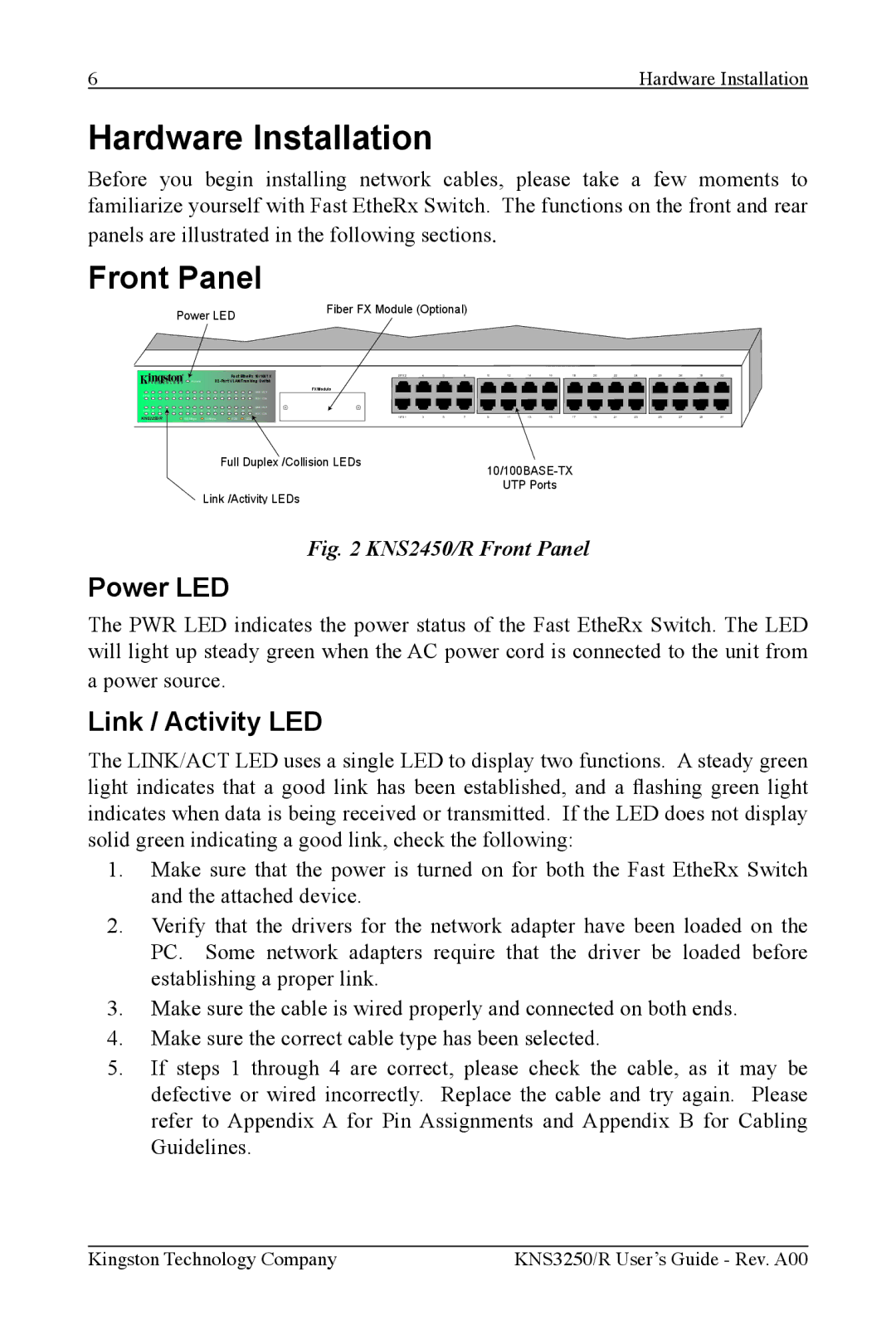
Before you begin installing network cables, please take a few moments to familiarize yourself with Fast EtheRx Switch. The functions on the front and rear panels are illustrated in the following sections.
Front Panel
Power LED
Fiber FX Module (Optional)
|
|
|
|
|
|
|
|
|
|
|
|
| Fast EtheRx 10/100TX | 2/FX2 | 4 | 6 | 8 | 10 | 12 | 14 | 16 | 18 | 20 | 22 | 24 | 26 | 28 | 30 | 32 | ||
|
|
|
|
|
|
| POWER |
|
|
|
|
|
|
|
|
|
|
|
|
|
|
|
|
| |||||||
|
|
|
|
|
|
|
|
|
|
|
|
|
|
| LINK / ACT | FX Module |
|
|
|
|
|
|
|
|
|
|
|
|
|
|
|
2/FX2 | 4 | 6 | 8 | 10 | 12 | 14 | 16 | 18 | 20 | 22 | 24 | 26 | 28 | 30 | 32 |
|
|
|
|
|
|
|
|
|
|
|
|
|
|
|
|
|
|
|
|
|
|
|
|
|
|
|
|
|
|
| FDX / COL |
|
|
|
|
|
|
|
|
|
|
|
|
|
|
|
|
|
|
|
|
|
|
|
|
|
|
|
|
|
|
| LINK / ACT |
|
|
|
|
|
|
|
|
|
|
|
|
|
|
|
|
1/FX1 | 3 | 5 | 7 | 9 | 11 | 13 | 15 | 17 | 19 | 21 | 23 | 25 | 27 | 29 | 31 |
|
|
|
|
|
|
|
|
|
|
|
|
|
|
|
|
|
|
|
|
|
|
|
|
|
|
|
|
|
|
| FDX / COL |
|
|
|
|
|
|
|
|
|
|
|
|
|
|
|
|
KNS3250/R |
|
|
| 100 Mbps |
| 10 Mbps |
|
| FDX |
| COL | 1/FX1 | 3 | 5 | 7 | 9 | 11 | 13 | 15 | 17 | 19 | 21 | 23 | 25 | 27 | 29 | 31 | ||||
Full Duplex /Collision LEDs
UTP Ports
Link /Activity LEDs
Fig. 2 KNS2450/R Front Panel
Power LED
The PWR LED indicates the power status of the Fast EtheRx Switch. The LED will light up steady green when the AC power cord is connected to the unit from a power source.
Link / Activity LED
The LINK/ACT LED uses a single LED to display two functions. A steady green light indicates that a good link has been established, and a ashing green light indicates when data is being received or transmitted. If the LED does not display solid green indicating a good link, check the following:
1.Make sure that the power is turned on for both the Fast EtheRx Switch and the attached device.
2.Verify that the drivers for the network adapter have been loaded on the PC. Some network adapters require that the driver be loaded before establishing a proper link.
3.Make sure the cable is wired properly and connected on both ends.
4.Make sure the correct cable type has been selected.
5.If steps 1 through 4 are correct, please check the cable, as it may be defective or wired incorrectly. Replace the cable and try again. Please refer to Appendix A for Pin Assignments and Appendix B for Cabling Guidelines.
Kingston Technology Company | KNS3250/R User’s Guide - Rev. A00 |
