Manuals
/
Kodak
/
Computer Equipment
/
All in One Printer
Kodak
8657 Understanding the Display Panel, A description of each item is on the following pages
Models:
8657
1
34
94
94
Download
94 pages
20.06 Kb
31
32
33
34
35
36
37
38
<
>
Troubleshooting
Specs
Install
Error codes
Configuring the Printer
Correcting Problems
Setup/Select
Selecting Defaults
Cleaning the Thermal Head
Weight
Page 34
Image 34
Getting Started
Understanding the Display Panel
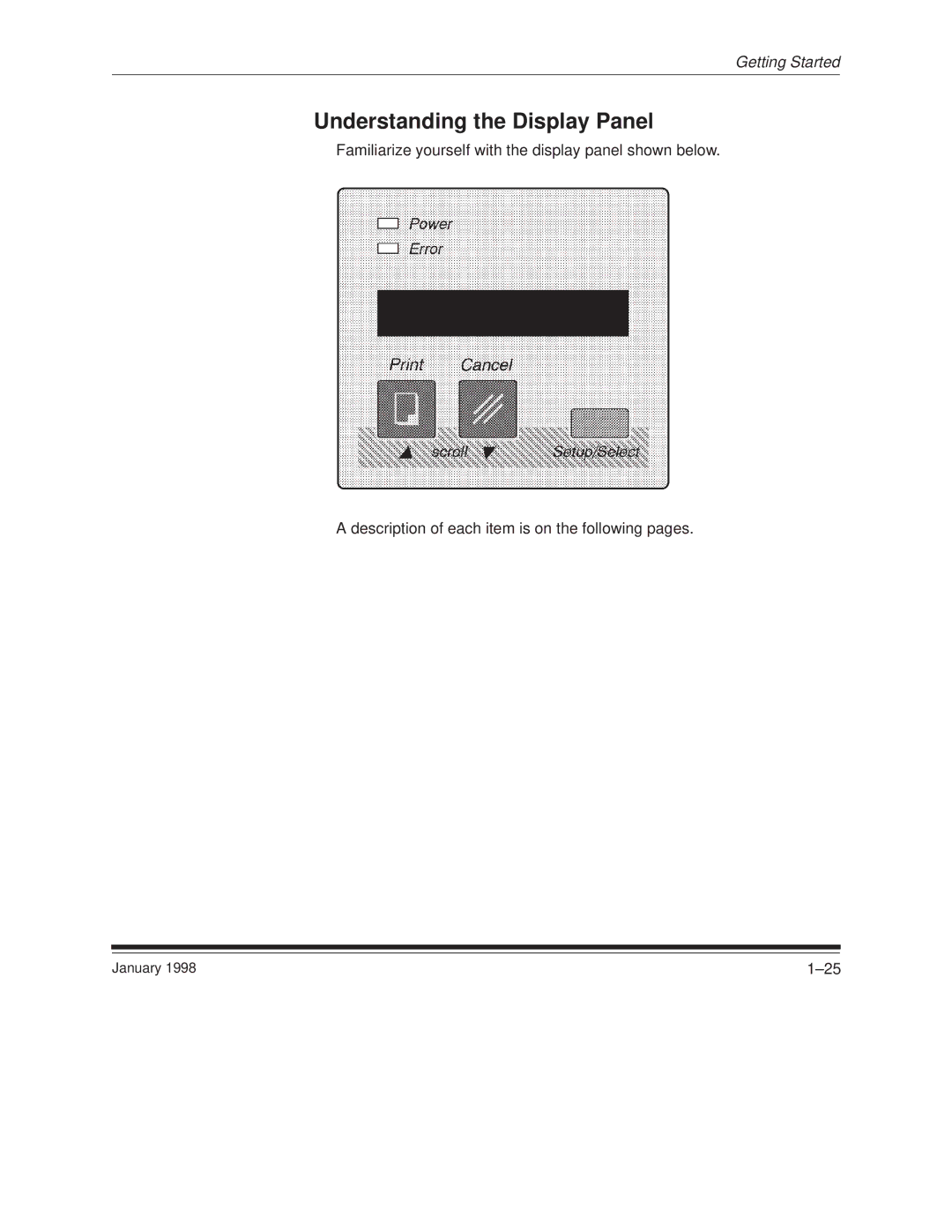
Familiarize yourself with the display panel shown below.
A description of each item is on the following pages.
January 1998
1±25
Page 33
Page 35
Page 34
Image 34
Page 33
Page 35
Contents
User’s Guide
KODAK PROFESSIONAL 8657 Printer
Part No. 3H0594
Checking Contents
Contents
Safety Regulations
Introduction
Page
Index
Introduction
About Your Printer
Host Interfaces
Introduction
Radio Frequency Interference
Regulatory Information
Safety Regulations
Head cleaning pads
Checking Contents
1 Getting Started
January
Removing the Shipping Pins
CAUTION Do not use the printer until you remove the shipping pins
Finding a Location
to allow room for
Printer Front View
Components of the Printer
Reviewing the Components
paper tray display panel
Getting Started
January
Printer Back View
The side of the printer is shown below
Printer Side View
power switch K number label
January
Printer Inside View
Power cord inlet
Attaching the Power Cord
January
Attaching the Interface Cable
Centronics Cable Parallel Connection
SCSI Cable
SCSI ports
An ADAPTEC SCSI host adapter board A SCSI terminator
Cleaning the Thermal Head
5. Open the cleaning pad
The cleaning pad may become discolored
About Ribbon
Printer Ribbon and Paper
Handling
Loading
8. Make sure that the spool notches are on the right
13. Fold any excess ribbon behind the adhesive strip
Getting Started
12. Remove the tape from the adhesive strip
1±19
15. Smooth the ribbon over the adhesive strip with your fingers
Getting Started
NOTE Keep the ribbon as straight as possible
16. Close the printer cover
Handling
About Paper
Loading
1. Remove the paper tray from the printer
7. Insert the paper tray in the printer until it locks into position
Getting Started
6. Press the latches on the front sides of the paper tray into place
8. Verify that the correct paper size is listed on the display panel
Turning on the Power
A description of each item is on the following pages
Understanding the Display Panel
Familiarize yourself with the display panel shown below
1±25
Power
Indicator Lights
Error
LCD Panel
Messages
Buttons
Cancel
Setup/Select
Print
Entering Setup Mode
Configuring the Printer
Using Setup Menus
Exiting Setup Mode
Restoring Factory Settings
Selecting Defaults
Selecting a Language for the Display Panel
Setting up a Parallel Connection
Specifying Port Information
Setting up an EtherTalk Connection
Setting up an IPX Novell NetWare Connection
Setting up a TCP/IP Connection
Select SCSIEXIT when you are done
Setting up a SCSI Connection
The new option will be in place once you exit Setup mode
Use the PORTSSCSI menu to change the SCSI port address
Making a Test Print
Printing
Job Scheduling
Storing Prints
2 Maintaining the Printer
Product
3 Supplies and Accessories
Ordering Supplies and Accessories
Part Number
Catalog
Paper
Paper Type
Number
Storing Supplies
Ribbon
Paper
For highest image quality, follow these paper storage instructions
4 Correcting Problems
Understanding Error Messages
Paper Size
Correcting Problems
Ribbon Type
Ribbon Type Mismatch
Symptom
Troubleshooting
Possible solutions
Symptom
Possible solutions
Possible solutions
Symptom
Multicolored spots appear
Symptom
Possible solutions
Handling for Humidity-related Paper Problems
Alternate Head Cleaning Instructions
4±10
8. Repeat steps 6 and 7 if you have a cleaning pad
Clearing the Paper Path
4±13
Correcting Problems
2. Gently pull paper up if it is caught inside the printer
January
4. Look in the tray area through the tray insertion slot
NOTE If you cannot remove the paper, service is required
Power Error
4±14
CAUTION The pins must be inserted exactly as described
Repacking the Printer
7. Put appliance filament tape over the cover of the printer
Correcting Problems
6. Close the printer cover
9. Pack the printer in its original box
Getting Help
Country
Asia/Pacific Helpline Numbers
European Helpline Numbers
Country code
Size
Appendix A Printer Specifications
Weight
Operating Environment
Power Consumption
Power Requirements
Voltage/Frequency
Setting up for the Installation
Appendix B Adding More Memory
Customizing Your Printer
2. Attach the wrist portion of a grounding strap to your wrist
Opening the Printer
2. Hold on to the two black handles on the metal plate and slowly pull the drawer out about three inches
4. Gently pull the ribbon cable out of the socket
Customizing Your Printer
January
Installing the Card
card clip
Closing the Printer
4. Close the drawer the rest of the way
7. Verify that the Power light is lit on the printers display panel
Customizing Your Printer
5. Replace the five screws that you removed
Windows Systems
Appendix C nneed nn
a. Press Setup/Select when READY-RASTER appears in the dis- play panel
Cable
Macintosh Systems
Computer Type
Terminator
2. Attach the SCSI cable and SCSI terminator
Index
Page
Page
Page
Page
Parallel cable, attaching, 1±10 Parallel connection printer modes for
Page
Page
Page
Voltage, A±2
Weight of the printer, A±1
Unpacking the printer, 1±1
Index±10