12. CH LEVEL A, 13. CH LEVEL B — VOCODER
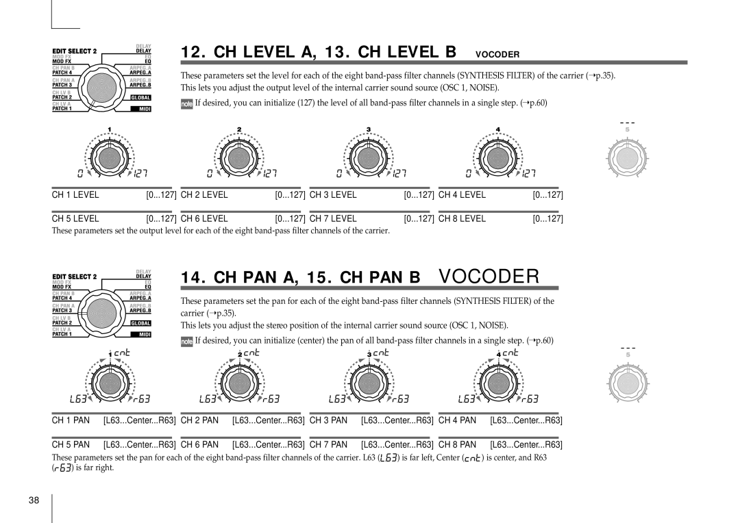
These parameters set the level for each of the eight
 If desired, you can initialize (127) the level of all
CH 1 LEVEL | [0... | 127] |
| CH 2 LEVEL | [0... | 127] |
| CH 3 LEVEL | [0... | 127] |
| CH 4 LEVEL | [0... | 127] |
|
|
|
|
|
|
|
|
|
|
|
|
|
|
|
CH 5 LEVEL | [0... | 127] |
| CH 6 LEVEL | [0... | 127] |
| CH 7 LEVEL | [0... | 127] |
| CH 8 LEVEL | [0... | 127] |
These parameters set the output level for each of the eight
14. CH PAN A, 15. CH PAN B — VOCODER
These parameters set the pan for each of the eight
This lets you adjust the stereo position of the internal carrier sound source (OSC 1, NOISE).
 If desired, you can initialize (center) the pan of all
CH 1 PAN | [L63... | Center... | R63] |
| CH 2 PAN | [L63... | Center... | R63] |
| CH 3 PAN | [L63... | Center... | R63] |
| CH 4 PAN | [L63... | Center... | R63] |
|
|
|
|
|
|
|
|
|
|
|
|
|
|
|
|
|
|
|
CH 5 PAN | [L63... | Center... | R63] |
| CH 6 PAN | [L63... | Center... | R63] |
| CH 7 PAN | [L63... | Center... | R63] |
| CH 8 PAN | [L63... | Center... | R63] |
These parameters set the pan for each of the eight 

 ) is far left, Center (

 ) is center, and R63
(

 ) is far right.
38