12. PATCH 1, 13. PATCH 2, 14. PATCH 3, 15. PATCH 4 — SYNTH
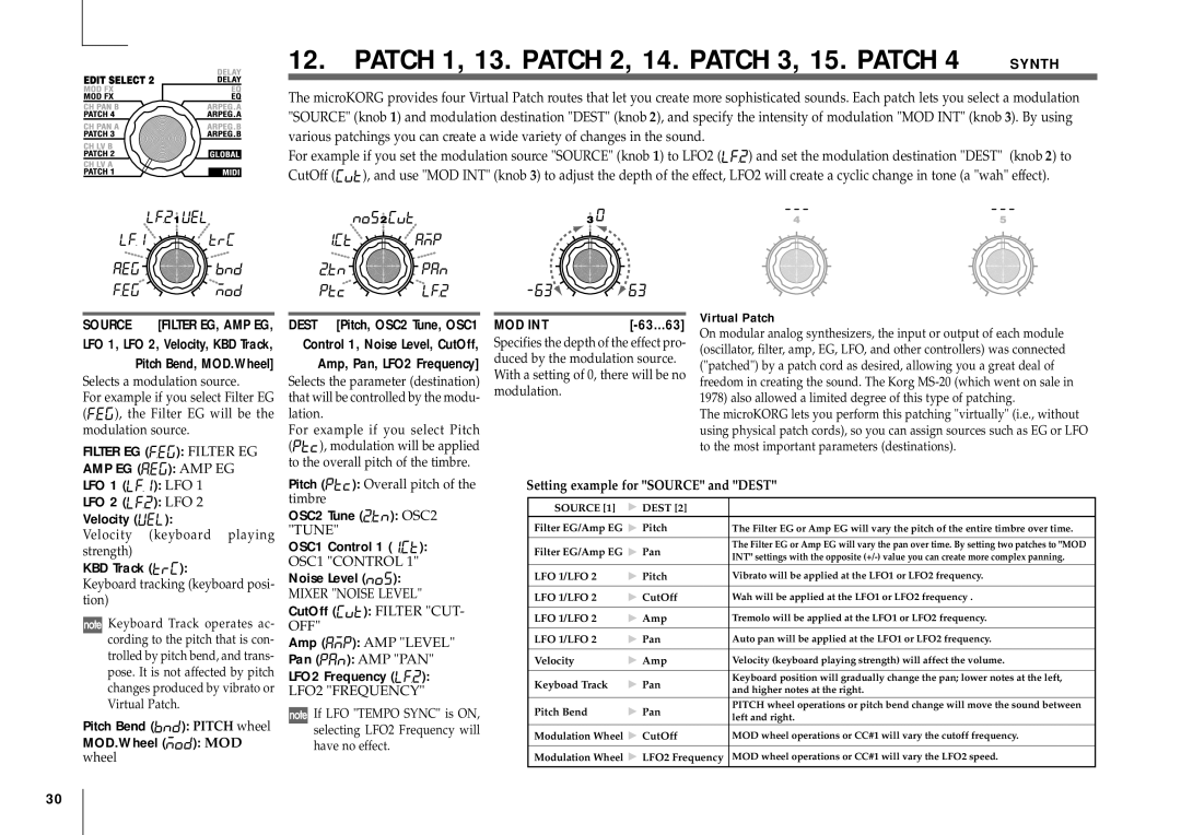
The microKORG provides four Virtual Patch routes that let you create more sophisticated sounds. Each patch lets you select a modulation "SOURCE" (knob 1) and modulation destination "DEST" (knob 2), and specify the intensity of modulation "MOD INT" (knob 3). By using various patchings you can create a wide variety of changes in the sound.
For example if you set the modulation source "SOURCE" (knob 1) to LFO2 (![]() ) and set the modulation destination "DEST" (knob 2) to
) and set the modulation destination "DEST" (knob 2) to
CutOff (![]() ), and use "MOD INT" (knob 3) to adjust the depth of the effect, LFO2 will create a cyclic change in tone (a "wah" effect).
), and use "MOD INT" (knob 3) to adjust the depth of the effect, LFO2 will create a cyclic change in tone (a "wah" effect).
SOURCE [FILTER EG, AMP EG,
LFO 1, LFO 2, Velocity, KBD Track,
Pitch Bend, MOD.Wheel]
Selects a modulation source.
For example if you select Filter EG
(![]()
![]()
![]() ), the Filter EG will be the modulation source.
), the Filter EG will be the modulation source.
FILTER EG (

 ): FILTER EG
AMP EG (![]()
![]()
![]() ): AMP EG
): AMP EG
DEST [Pitch, OSC2 Tune, OSC1
Control 1, Noise Level, CutOff,
Amp, Pan, LFO2 Frequency]
Selects the parameter (destination) that will be controlled by the modu- lation.
For example if you select Pitch
(![]()
![]()
![]() ), modulation will be applied to the overall pitch of the timbre.
), modulation will be applied to the overall pitch of the timbre.
MOD INT |
|
Specifies the depth of the effect pro- duced by the modulation source. With a setting of 0, there will be no modulation.
Virtual Patch
On modular analog synthesizers, the input or output of each module (oscillator, filter, amp, EG, LFO, and other controllers) was connected ("patched") by a patch cord as desired, allowing you a great deal of freedom in creating the sound. The Korg
The microKORG lets you perform this patching "virtually" (i.e., without using physical patch cords), so you can assign sources such as EG or LFO to the most important parameters (destinations).
LFO 1 (![]()
![]()
![]() ): LFO 1
): LFO 1
LFO 2 (![]()
![]()
![]() ): LFO 2
): LFO 2
Velocity (![]()
![]()
![]() ):
):
Velocity (keyboard playing strength)
KBD Track (![]()
![]()
![]() ):
):
Keyboard tracking (keyboard posi- tion)
![]() Keyboard Track operates ac- cording to the pitch that is con- trolled by pitch bend, and trans- pose. It is not affected by pitch changes produced by vibrato or Virtual Patch.
Keyboard Track operates ac- cording to the pitch that is con- trolled by pitch bend, and trans- pose. It is not affected by pitch changes produced by vibrato or Virtual Patch.
Pitch Bend (![]()
![]()
![]() ): PITCH wheel
): PITCH wheel
MOD.Wheel (![]()
![]()
![]() ): MOD wheel
): MOD wheel
Pitch (![]()
![]()
![]() ): Overall pitch of the timbre
): Overall pitch of the timbre
OSC2 Tune (![]()
![]()
![]() ): OSC2 "TUNE"
): OSC2 "TUNE"
OSC1 Control 1 (![]()
![]()
![]() ):
):
OSC1 "CONTROL 1"
Noise Level (![]()
![]()
![]() ):
):
MIXER "NOISE LEVEL"
CutOff (![]()
![]()
![]() ): FILTER "CUT-
): FILTER "CUT-
OFF"
Amp (![]()
![]()
![]() ): AMP "LEVEL"
): AMP "LEVEL"
Pan (![]()
![]()
![]() ): AMP "PAN"
): AMP "PAN"
LFO2 Frequency (![]()
![]() ):
):
LFO2 "FREQUENCY"
![]() If LFO "TEMPO SYNC" is ON, selecting LFO2 Frequency will have no effect.
If LFO "TEMPO SYNC" is ON, selecting LFO2 Frequency will have no effect.
Setting example for "SOURCE" and "DEST"
SOURCE [1] | DEST [2] |
| |
Filter EG/Amp EG | Pitch | The Filter EG or Amp EG will vary the pitch of the entire timbre over time. | |
|
|
| |
Filter EG/Amp EG | Pan | The Filter EG or Amp EG will vary the pan over time. By setting two patches to "MOD | |
INT" settings with the opposite | |||
|
| ||
LFO 1/LFO 2 | Pitch | Vibrato will be applied at the LFO1 or LFO2 frequency. | |
|
|
| |
LFO 1/LFO 2 | CutOff | Wah will be applied at the LFO1 or LFO2 frequency . | |
|
|
| |
LFO 1/LFO 2 | Amp | Tremolo will be applied at the LFO1 or LFO2 frequency. | |
|
|
| |
LFO 1/LFO 2 | Pan | Auto pan will be applied at the LFO1 or LFO2 frequency. | |
|
|
| |
Velocity | Amp | Velocity (keyboard playing strength) will affect the volume. | |
|
|
| |
Keyboad Track | Pan | Keyboard position will gradually change the pan; lower notes at the left, | |
and higher notes at the right. | |||
|
| ||
Pitch Bend | Pan | PITCH wheel operations or pitch bend change will move the sound between | |
left and right. | |||
|
| ||
Modulation Wheel | CutOff | MOD wheel operations or CC#1 will vary the cutoff frequency. | |
|
|
| |
Modulation Wheel | LFO2 Frequency | MOD wheel operations or CC#1 will vary the LFO2 speed. | |
|
|
|
30
