Communication Protocol
13 Communication Protocol
This protocol, which enables
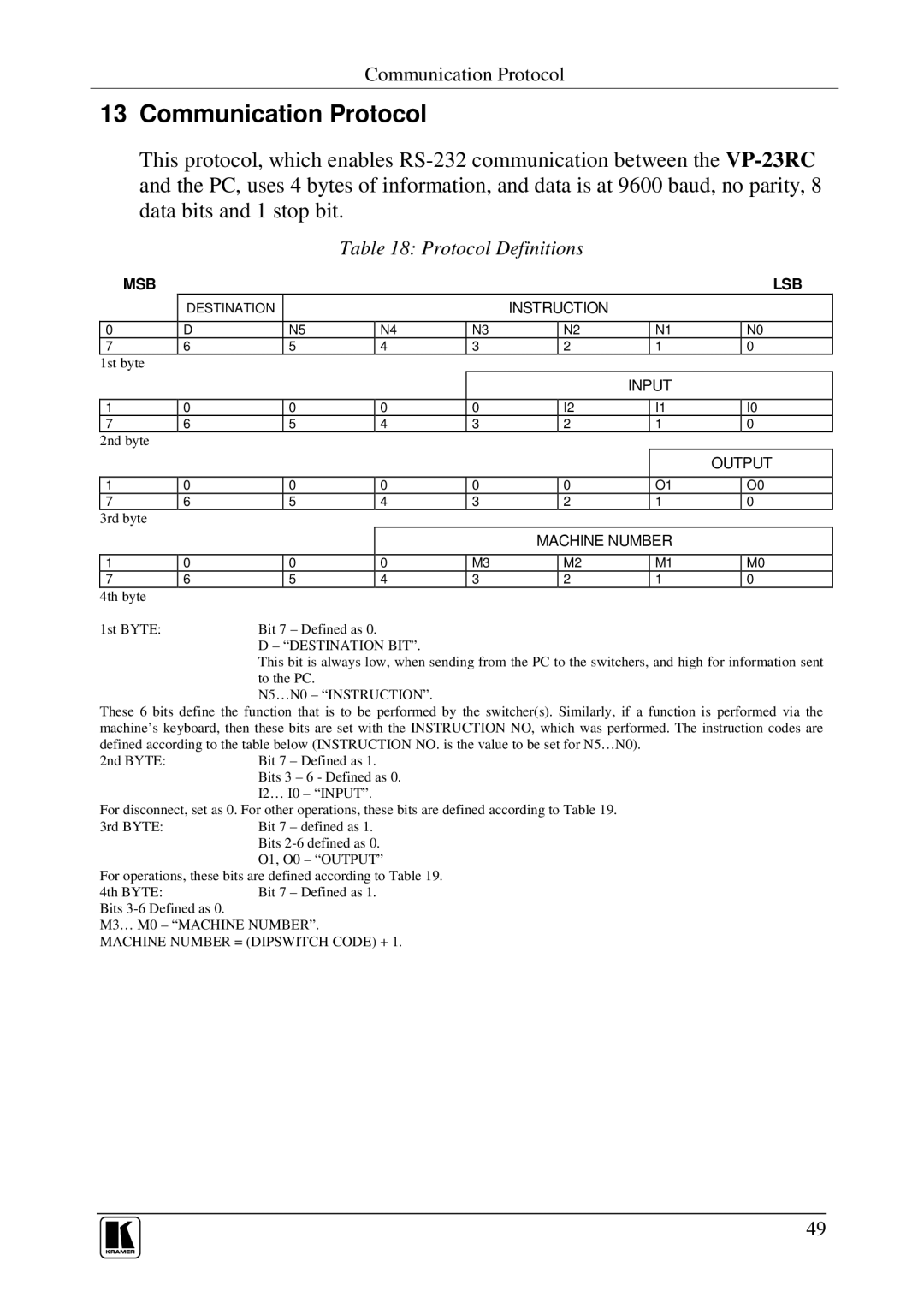
Table 18: Protocol Definitions
| MSB |
|
|
|
|
|
|
|
|
|
| LSB |
|
| DESTINATION |
|
|
| INSTRUCTION |
|
|
|
| ||
|
|
|
|
|
|
|
|
|
|
|
|
|
0 | D |
| N5 | N4 | N3 |
| N2 |
| N1 |
| N0 | |
7 | 6 |
| 5 | 4 | 3 |
| 2 |
| 1 |
| 0 | |
1st byte |
|
|
|
|
|
|
|
|
|
|
| |
|
|
|
|
|
|
|
|
| INPUT |
|
| |
|
|
|
|
|
|
|
|
|
|
|
| |
1 | 0 |
| 0 | 0 | 0 |
| I2 |
| I1 |
| I0 | |
7 | 6 |
| 5 | 4 | 3 |
| 2 |
| 1 |
| 0 | |
2nd byte |
|
|
|
|
|
|
|
|
|
|
| |
|
|
|
|
|
|
|
|
|
|
| OUTPUT | |
|
|
|
|
|
|
|
|
|
| |||
| 1 | 0 |
| 0 | 0 | 0 |
| 0 |
| O1 |
| O0 |
7 | 6 |
| 5 | 4 | 3 |
| 2 |
| 1 |
| 0 | |
3rd byte |
|
|
|
|
|
|
|
|
|
|
| |
|
|
|
|
|
|
| MACHINE NUMBER |
|
| |||
|
|
|
|
|
|
|
|
|
|
| ||
| 1 | 0 |
| 0 | 0 | M3 |
| M2 |
| M1 |
| M0 |
7 | 6 |
| 5 | 4 | 3 |
| 2 |
| 1 |
| 0 | |
4th byte |
|
|
|
|
|
|
|
|
|
|
| |
1st BYTE: |
| Bit 7 ± Defined as 0. |
|
|
|
|
|
|
|
| ||
|
|
| D ± ª DESTINATION BITº . |
|
|
|
|
|
|
| ||
|
|
| This bit is always low, when sending from the PC to the switchers, and high for information sent | |||||||||
|
|
| to the PC. |
|
|
|
|
|
|
|
| |
|
|
| N5…N0 ± ª INSTRUCTIONº . |
|
|
|
|
|
|
| ||
These 6 bits define the function that is to be performed by the switcher(s). Similarly, if a function is performed via the machine’s keyboard, then these bits are set with the INSTRUCTION NO, which was performed. The instruction codes are defined according to the table below (INSTRUCTION NO. is the value to be set for N5…N0).
2nd BYTE: | Bit 7 ± Defined as 1. |
| Bits 3 ± 6 - Defined as 0. |
| I2… I0 ± ª INPUTº . |
For disconnect, set as 0. For other operations, these bits are defined according to Table 19.
3rd BYTE: | Bit 7 ± defined as 1. |
| Bits |
| O1, O0 ± ª OUTPUTº |
For operations, these bits are defined according to Table 19.
4th BYTE:Bit 7 ± Defined as 1. Bits
M3… M0 ± ª MACHINE NUMBERº .
MACHINE NUMBER = (DIPSWITCH CODE) + 1.
49