Operating Your VP-23RC
Projector
Lift
Projector
Blinds
Player
 INTERNET
Screen  Composite
Video Player
Lighting
System
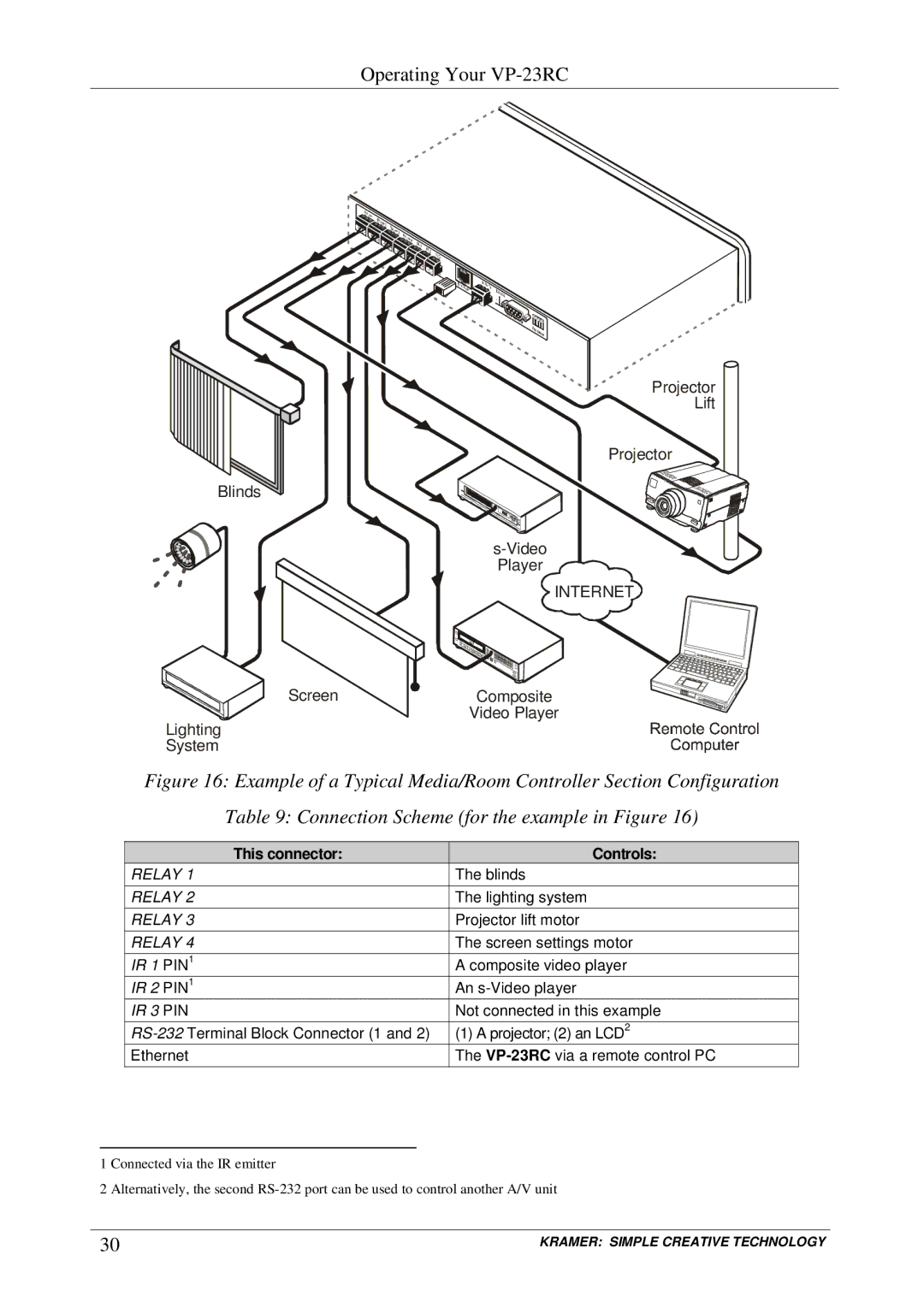
Figure 16: Example of a Typical Media/Room Controller Section Configuration
Table 9: Connection Scheme (for the example in Figure 16)
| This connector: | Controls: |
RELAY 1 | The blinds | |
RELAY 2 | The lighting system | |
RELAY 3 | Projector lift motor | |
RELAY 4 | The screen settings motor | |
IR 1 | PIN1 | A composite video player |
IR 2 | PIN1 | An |
IR 3 | PIN | Not connected in this example |
(1) A projector; (2) an LCD2 | ||
Ethernet | The | |
1 Connected via the IR emitter
2 Alternatively, the second
30 | KRAMER: SIMPLE CREATIVE TECHNOLOGY |