GAUGE SET
CONNECTIONS FOR OPTIMIZING SYSTEM CHARGE
MANIFOLD GAUGE SET
LOW HIGH
B TRUE SUCTION PORT
CONNECTION
NOTE
turned right−side−up to deliver vapor during charge optimizing procedure.
REFRIGERANT
TANK
CHARGE IN | A |
LIQUID PHASE |
|
DIGITAL SCALE |
|
TO LIQUID
LINE SERVICEVALVE C
![]() D
D
OUTDOOR UNIT
TEMPERATURE SENSOR
(LIQUID LINE)
TEMPERATURE SENSOR (USE FOR
SUBCOOLING METHOD)
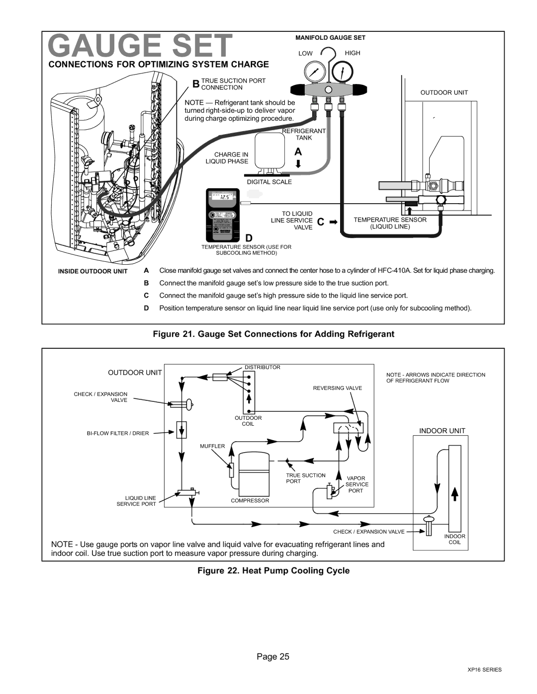
INSIDE OUTDOOR UNIT | A Close manifold gauge set valves and connect the center hose to a cylinder of HFC−410A. Set for liquid phase charging. |
BConnect the manifold gauge set’s low pressure side to the true suction port.
CConnect the manifold gauge set’s high pressure side to the liquid line service port.
DPosition temperature sensor on liquid line near liquid line service port (use only for subcooling method).
Figure 21. Gauge Set Connections for Adding Refrigerant
OUTDOOR UNIT | DISTRIBUTOR |
|
| NOTE − ARROWS INDICATE DIRECTION | |
|
| |
|
| OF REFRIGERANT FLOW |
| REVERSING VALVE | |
CHECK / EXPANSION |
|
|
VALVE |
|
|
| OUTDOOR |
|
| COIL |
|
BI−FLOW FILTER / DRIER |
| INDOOR UNIT |
|
| |
| MUFFLER |
|
| TRUE SUCTION | VAPOR |
| PORT | |
| SERVICE | |
|
| |
|
| PORT |
LIQUID LINE | COMPRESSOR |
|
SERVICE PORT |
| |
|
| |
|
| CHECK / EXPANSION VALVE |
INDOOR
NOTE − Use gauge ports on vapor line valve and liquid valve for evacuating refrigerant lines andCOIL indoor coil. Use true suction port to measure vapor pressure during charging.
Figure 22. Heat Pump Cooling Cycle
Page 25
XP16 SERIES
