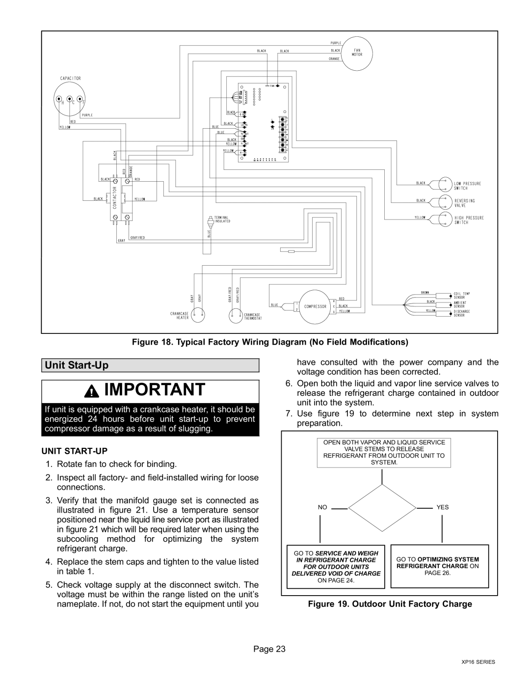
Figure 18. Typical Factory Wiring Diagram (No Field Modifications)
Unit Start−Up
have consulted with the power company and the voltage condition has been corrected.
![]() IMPORTANT
IMPORTANT
If unit is equipped with a crankcase heater, it should be energized 24 hours before unit start−up to prevent compressor damage as a result of slugging.
UNIT START−UP
1.Rotate fan to check for binding.
2.Inspect all factory− and field−installed wiring for loose connections.
3.Verify that the manifold gauge set is connected as illustrated in figure 21. Use a temperature sensor positioned near the liquid line service port as illustrated in figure 21 which will be required later when using the subcooling method for optimizing the system refrigerant charge.
4.Replace the stem caps and tighten to the value listed in table 1.
5.Check voltage supply at the disconnect switch. The voltage must be within the range listed on the unit’s nameplate. If not, do not start the equipment until you
6.Open both the liquid and vapor line service valves to release the refrigerant charge contained in outdoor unit into the system.
7.Use figure 19 to determine next step in system preparation.
OPEN BOTH VAPOR AND LIQUID SERVICE | ||
| VALVE STEMS TO RELEASE | |
REFRIGERANT FROM OUTDOOR UNIT TO | ||
| SYSTEM. | |
NO | PRESENT | YES |
|
| |
GO TO SERVICE AND WEIGH |
| |
IN REFRIGERANT CHARGE | GO TO OPTIMIZING SYSTEM | |
FOR OUTDOOR UNITS | REFRIGERANT CHARGE ON | |
DELIVERED VOID OF CHARGE | PAGE 26. | |
ON PAGE 24. |
| |
Figure 19. Outdoor Unit Factory Charge
Page 23
XP16 SERIES