Manuals
/
Lenox
/
Household Appliance
/
Air Conditioner
Lenox
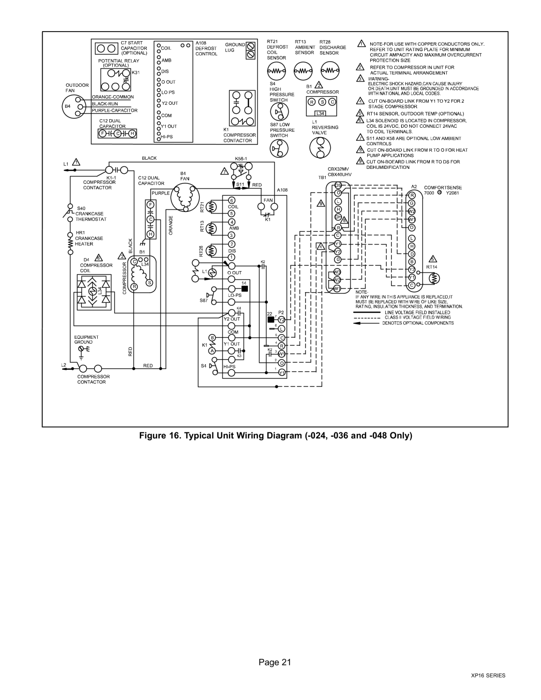
Elite Series XP16 Units Heat Pumps Typical Unit Wiring Diagram −024, −036 and −048 Only
Models:
Elite Series XP16 Units Heat Pumps
P506640-01
1
21
43
43
Download
43 pages
56.47 Kb
18
19
20
21
22
23
24
25
Install
Delay
Typical Field Wiring
Dimension
Maintenance
Brazing Procedures
Adjusting Indoor Airflow
3RECOVERING Refrigerant
Temperature Pressures
New Outdoor Unit Placement
Page 21
Image 21
Figure 16. Typical Unit Wiring Diagram (−024, −036 and −048 Only)
Page 21
XP16 SERIES
Page 20
Page 22
Page 21
Image 21
Page 20
Page 22
Contents
Table of Contents
Shipping and Packing List
General
Model Number Identification
Unit Dimensions − inches mm
Side View
XP16−024 Base Section XP16 Base with Legs
Typical Unit Parts Arrangement
Caps and Fasteners Torque Requirements
Detail a
Operating Service Valves
Operating Gauge Set and Service Valves
Using Manifold Gauge SET
To Access Service Port Operating Ball−Type Service Valve
1DISCONNECT Power
Recovering Refrigerant from Existing System
3RECOVERING Refrigerant
Method Method 2 Limitations
New Outdoor Unit Placement
Placement, Slab Mounting and Stabilizing Unit
Detail a Outside Unit Placement
Removing and Installing Panels
Louvered Panel Installation
Louvered Panel Removal
Using Existing Line SET
NEW or Replacement Line SET Installation
Line Set Requirements
Adding Polyol Ester OIL Requirements
Refrigerant Line SET Alling Horizontal Runs
Refrigerant Line SET From Vertical to Horizontal
Brazing Connections
1CUT and Debur
Brazing Procedures
Flow Nitrogen
Wrap Service Valves
6BRAZE Line SET
7PREPARATION for Next Step
2CONNECT Gauges and Equipment for Flushing Procedure
Indoor Expansion Valve Installation
Installing New Indoor Metering Device
Sensing Bulb Installation
Equalizer Line Installation
Test for Leaks
S S S
Evacuating Line Set and Indoor Coil
2INSTALL Thermostat
Size Circuit and Install Disconnect
Electrical Connections
24VAC Transformer
LOW Voltage Connections
4HIGH Voltage Power Supply Connections
Typical Field Wiring
Typical Unit Wiring Diagram −024, −036 and −048 Only
Typical Unit Wiring Diagram −060 Only
Unit START−UP
Unit Start−Up
Leak CHECK, Repair and Evacuate
Connect Manifold Gauge SET and Weigh in Charge
Calculating System Charge for Outdoor Unit Void of Charge
Indoor Unit
Connections for Optimizing System Charge
Optimizing Procedure
Adjusting Indoor Airflow
Optimizing System Refrigerant Charge
SATº
LIQº
SCº =
XP16−036−230
XP16−048−230
XP16−060−230
Normal Operating Pressures
Temperature Pressures
Unit Components
System Operation
DS2 Green LED FAN TWO Connectors
Delay
Test
24VAC
DS2 DS1
Demand Defrost Control A108 Diagnostic Leds
Slow
OFF
SECOND−STAGE Operation
Defrost System
Defrost Control CONNECTIONS, Jumpers Settings and Features
Emergency Heat Amber Light
Defrost System Overview
Compressor Delay Mode P5
Operational Mode Overview
Defrost Cycle Actuation
Temperature Mode TIME/TEMPERATURE Mode
Demand Mode Thirty 30 Minute Time
Defrost
HOW did Defrost TERMINATE?
Degrees Resistance Fahrenheit 136.3 2680
High Discharge Sensor RT28 Temperature / Resistance Range
S S
Test Pin P1 Functions
Procedure
Maintenance
Two−Stage Modulation Compressors Checks
Tools Required
Homeowner
Compressor
Temperature
Outdoor Unit FAN Motor
Pressures
Cooling Mode
XP16 Start−Up and Performance
Start UP Checks
Top
Page
Image
Contents