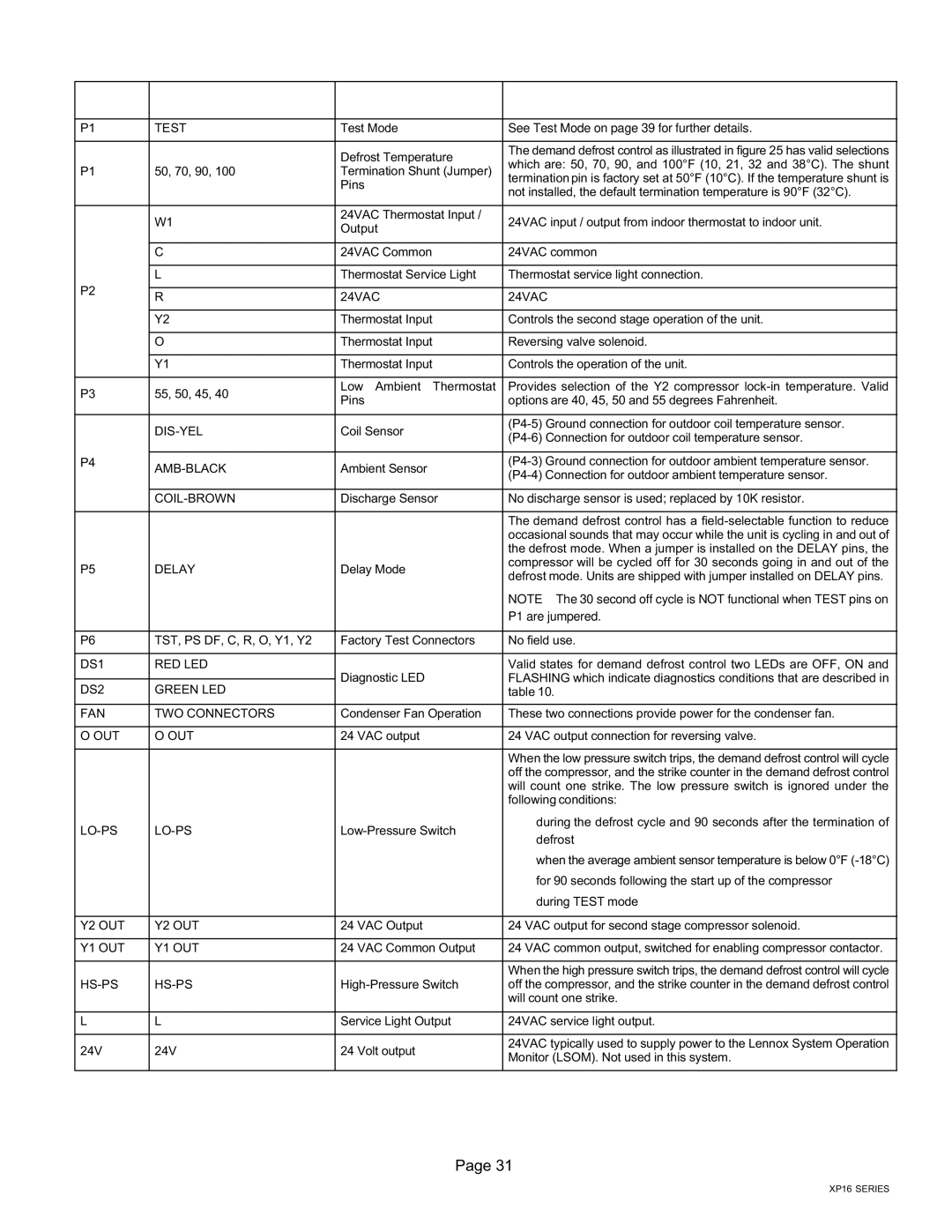
Table 9. Demand Defrost Control (A108) Inputs, Outputs and Configurable Settings
Control | Control Label or | Purpose | Function | ||
Locations | Description | ||||
|
|
| |||
|
|
|
| ||
P1 | TEST | Test Mode | See Test Mode on page 39 for further details. | ||
|
|
|
| ||
|
| Defrost Temperature | The demand defrost control as illustrated in figure 25 has valid selections | ||
|
| which are: 50, 70, 90, and 100°F (10, 21, 32 and 38°C). The shunt | |||
P1 | 50, 70, 90, 100 | Termination Shunt (Jumper) | |||
termination pin is factory set at 50°F (10°C). If the temperature shunt is | |||||
|
| Pins | |||
|
| not installed, the default termination temperature is 90°F (32°C). | |||
|
|
| |||
|
|
|
|
| |
| W1 | 24VAC Thermostat Input / | 24VAC input / output from indoor thermostat to indoor unit. | ||
| Output | ||||
|
|
|
| ||
|
|
|
| ||
| C | 24VAC Common | 24VAC common | ||
|
|
|
| ||
| L | Thermostat Service Light | Thermostat service light connection. | ||
P2 |
|
|
|
| |
R | 24VAC | 24VAC | |||
| |||||
|
|
|
| ||
| Y2 | Thermostat Input | Controls the second stage operation of the unit. | ||
|
|
|
| ||
| O | Thermostat Input | Reversing valve solenoid. | ||
|
|
|
| ||
| Y1 | Thermostat Input | Controls the operation of the unit. | ||
|
|
|
| ||
P3 | 55, 50, 45, 40 | Low Ambient Thermostat | Provides selection of the Y2 compressor lock−in temperature. Valid | ||
Pins | options are 40, 45, 50 and 55 degrees Fahrenheit. | ||||
|
| ||||
|
|
|
| ||
| DIS−YEL | Coil Sensor | (P4−5) Ground connection for outdoor coil temperature sensor. | ||
| (P4−6) Connection for outdoor coil temperature sensor. | ||||
|
|
| |||
|
|
|
| ||
P4 | AMB−BLACK | Ambient Sensor | (P4−3) Ground connection for outdoor ambient temperature sensor. | ||
| (P4−4) Connection for outdoor ambient temperature sensor. | ||||
|
|
| |||
|
|
|
| ||
| COIL−BROWN | Discharge Sensor | No discharge sensor is used; replaced by 10K resistor. | ||
|
|
|
| ||
|
|
| The demand defrost control has a field−selectable function to reduce | ||
|
|
| occasional sounds that may occur while the unit is cycling in and out of | ||
|
|
| the defrost mode. When a jumper is installed on the DELAY pins, the | ||
P5 | DELAY | Delay Mode | compressor will be cycled off for 30 seconds going in and out of the | ||
defrost mode. Units are shipped with jumper installed on DELAY pins. | |||||
|
|
| |||
|
|
| NOTE − The 30 second off cycle is NOT functional when TEST pins on | ||
|
|
| P1 are jumpered. | ||
|
|
|
| ||
P6 | TST, PS DF, C, R, O, Y1, Y2 | Factory Test Connectors | No field use. | ||
|
|
|
| ||
DS1 | RED LED |
| Valid states for demand defrost control two LEDs are OFF, ON and | ||
|
| Diagnostic LED | FLASHING which indicate diagnostics conditions that are described in | ||
DS2 | GREEN LED | ||||
| table 10. | ||||
|
|
|
| ||
FAN | TWO CONNECTORS | Condenser Fan Operation | These two connections provide power for the condenser fan. | ||
|
|
|
| ||
O OUT | O OUT | 24 VAC output | 24 VAC output connection for reversing valve. | ||
|
|
|
| ||
|
|
| When the low pressure switch trips, the demand defrost control will cycle | ||
|
|
| off the compressor, and the strike counter in the demand defrost control | ||
|
|
| will count one strike. The low pressure switch is ignored under the | ||
|
|
| following conditions: | ||
LO−PS | LO−PS | Low−Pressure Switch | S | during the defrost cycle and 90 seconds after the termination of | |
| defrost | ||||
|
|
|
| ||
|
|
| S when the average ambient sensor temperature is below 0°F (−18°C) | ||
|
|
| S for 90 seconds following the start up of the compressor | ||
|
|
| S | during TEST mode | |
|
|
|
| ||
Y2 OUT | Y2 OUT | 24 VAC Output | 24 VAC output for second stage compressor solenoid. | ||
|
|
|
| ||
Y1 OUT | Y1 OUT | 24 VAC Common Output | 24 VAC common output, switched for enabling compressor contactor. | ||
|
|
|
| ||
|
|
| When the high pressure switch trips, the demand defrost control will cycle | ||
HS−PS | HS−PS | High−Pressure Switch | off the compressor, and the strike counter in the demand defrost control | ||
|
|
| will count one strike. | ||
|
|
|
| ||
L | L | Service Light Output | 24VAC service light output. | ||
|
|
|
| ||
24V | 24V | 24 Volt output | 24VAC typically used to supply power to the Lennox System Operation | ||
Monitor (LSOM). Not used in this system. | |||||
|
|
| |||
|
|
|
|
| |
Page 31
XP16 SERIES