Operation
3.2.14Alarm and Status Messages
Module Status Messages
The module status messages indicate how many UPS modules are included in the system and the present status of each module.
The following status messages may appear in the module status area.
1.MOD N: A module status message line is displayed for each UPS module in the system. Up to six
(6) modules may be included in a
2.ON LINE: The UPS module output circuit breaker is closed and power from the module is available to the SCC. The module output is sharing the critical load if the UPS Output Breaker is closed.
3.
4.SUM ALM: The Module Summary Alarm has been activated by one of the alarm messages listed in two
5.COM FAIL: The UPS module is not communicating with the SCC. This could mean loss of power to the UPS module controls, a disconnected cable or a control logic failure (detected by watchdog timer. Call Liebert Global Services if you require assistance. To resume communication after control power is restored, sequence display to Master Menu.
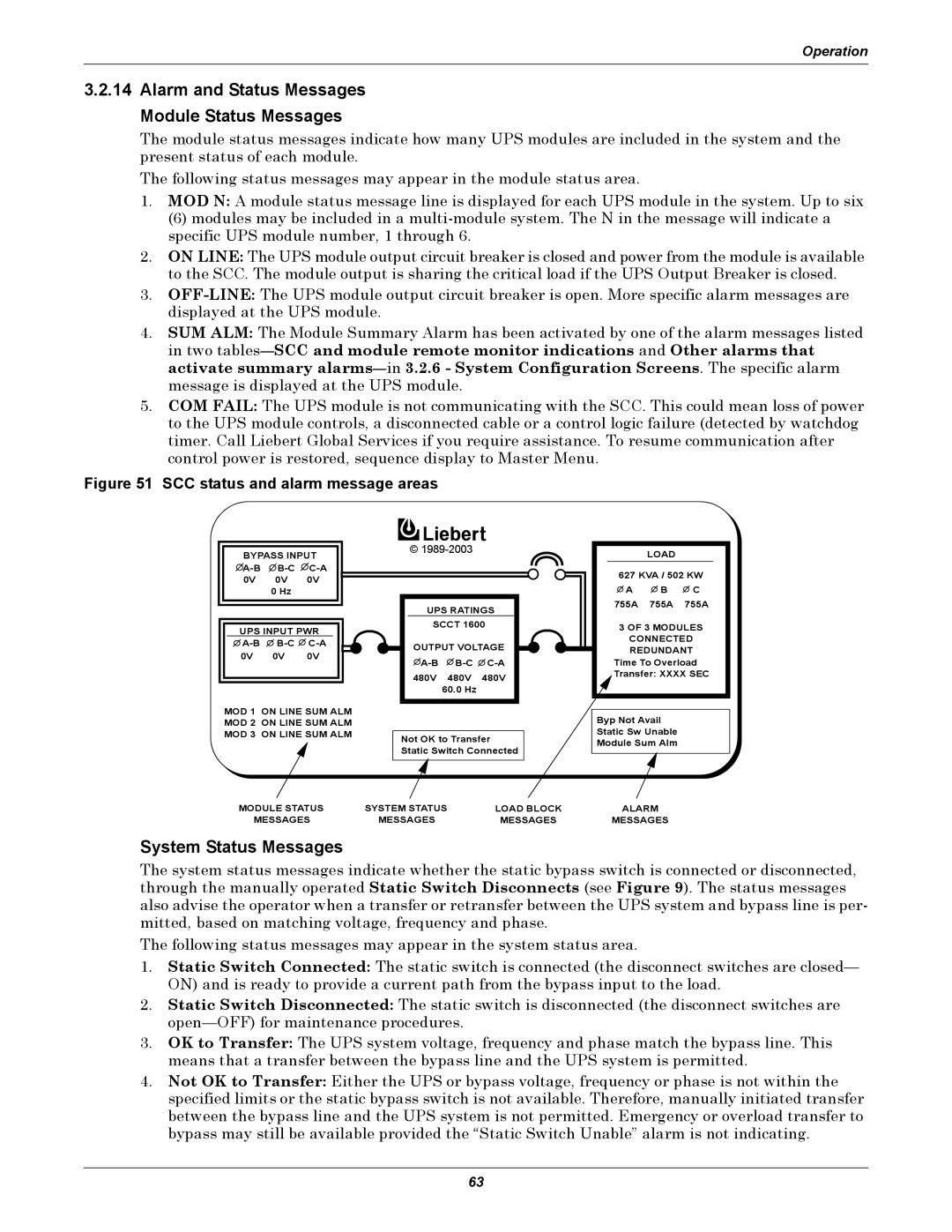
Figure 51 SCC status and alarm message areas
BYPASS INPUT ![]() A-B
A-B![]() B-C
B-C![]() C-A
C-A
0V 0V 0V
0 Hz
UPS INPUT PWR ![]()
![]()
![]()
0V 0V 0V
MOD 1 ON LINE SUM ALM MOD 2 ON LINE SUM ALM MOD 3 ON LINE SUM ALM
© 1989-2003
UPS RATINGS
SCCT 1600
OUTPUT VOLTAGE
![]() A-B
A-B![]()
![]()
480V 480V 480V
60.0 Hz
Not OK to Transfer
Static Switch Connected
LOAD
627 KVA / 502 KW ![]() A
A ![]() B
B ![]() C 755A 755A 755A
C 755A 755A 755A
3 OF 3 MODULES
CONNECTED
REDUNDANT Time To Overload Transfer: XXXX SEC
Byp Not Avail
Static Sw Unable
Module Sum Alm
MODULE STATUS | SYSTEM STATUS | LOAD BLOCK | ALARM |
MESSAGES | MESSAGES | MESSAGES | MESSAGES |
System Status Messages
The system status messages indicate whether the static bypass switch is connected or disconnected, through the manually operated Static Switch Disconnects (see Figure 9). The status messages also advise the operator when a transfer or retransfer between the UPS system and bypass line is per- mitted, based on matching voltage, frequency and phase.
The following status messages may appear in the system status area.
1.Static Switch Connected: The static switch is connected (the disconnect switches are closed— ON) and is ready to provide a current path from the bypass input to the load.
2.Static Switch Disconnected: The static switch is disconnected (the disconnect switches are
3.OK to Transfer: The UPS system voltage, frequency and phase match the bypass line. This means that a transfer between the bypass line and the UPS system is permitted.
4.Not OK to Transfer: Either the UPS or bypass voltage, frequency or phase is not within the specified limits or the static bypass switch is not available. Therefore, manually initiated transfer between the bypass line and the UPS system is not permitted. Emergency or overload transfer to bypass may still be available provided the “Static Switch Unable” alarm is not indicating.
63