Operation
•Battery Test (MMU
•Battery Temp Compensation Charging (MMU
3.2.2SCC Monitor/Mimic Display Screen
From SCC Master Menu move the highlighted cursor to MONITOR/MIMIC DISPLAY. Press the Select pad and the Monitor/Mimic screen is displayed.
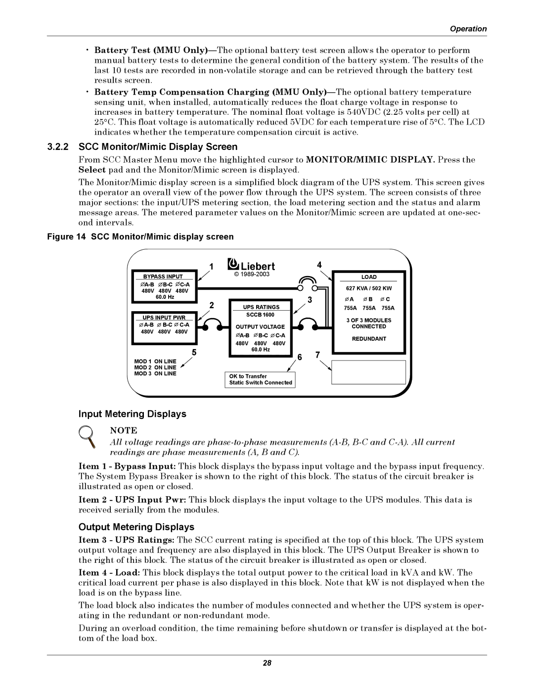
The Monitor/Mimic display screen is a simplified block diagram of the UPS system. This screen gives the operator an overall view of the power flow through the UPS system. The screen consists of three major sections: the input/UPS metering section, the load metering section and the status and alarm message areas. The metered parameter values on the Monitor/Mimic screen are updated at
Figure 14 SCC Monitor/Mimic display screen
1
BYPASS INPUT
![]() A-B
A-B![]() B-C
B-C![]() C-A
C-A
2
UPS INPUT PWR ![]()
![]()
![]()
5
MOD 1 ON LINE
MOD 2 ON LINE
MOD 3 ON LINE
© 1989-2003
UPS RATINGS
SCCB 1600
OUTPUT VOLTAGE ![]() A-B
A-B![]() B-C
B-C![]()
480V 480V 480V
60.0 Hz
OK to Transfer
Static Switch Connected
4
3
67
LOAD
627 KVA / 502 KW
![]() A
A ![]() B
B ![]() C 755A 755A 755A
C 755A 755A 755A
3 OF 3 MODULES
CONNECTED
REDUNDANT
Input Metering Displays
NOTE
All voltage readings are
Item 1 - Bypass Input: This block displays the bypass input voltage and the bypass input frequency. The System Bypass Breaker is shown to the right of this block. The status of the circuit breaker is illustrated as open or closed.
Item 2 - UPS Input Pwr: This block displays the input voltage to the UPS modules. This data is received serially from the modules.
Output Metering Displays
Item 3 - UPS Ratings: The SCC current rating is specified at the top of this block. The UPS system output voltage and frequency are also displayed in this block. The UPS Output Breaker is shown to the right of this block. The status of the circuit breaker is illustrated as open or closed.
Item 4 - Load: This block displays the total output power to the critical load in kVA and kW. The critical load current per phase is also displayed in this block. Note that kW is not displayed when the load is on the bypass line.
The load block also indicates the number of modules connected and whether the UPS system is oper- ating in the redundant or
During an overload condition, the time remaining before shutdown or transfer is displayed at the bot- tom of the load box.
28