Operation
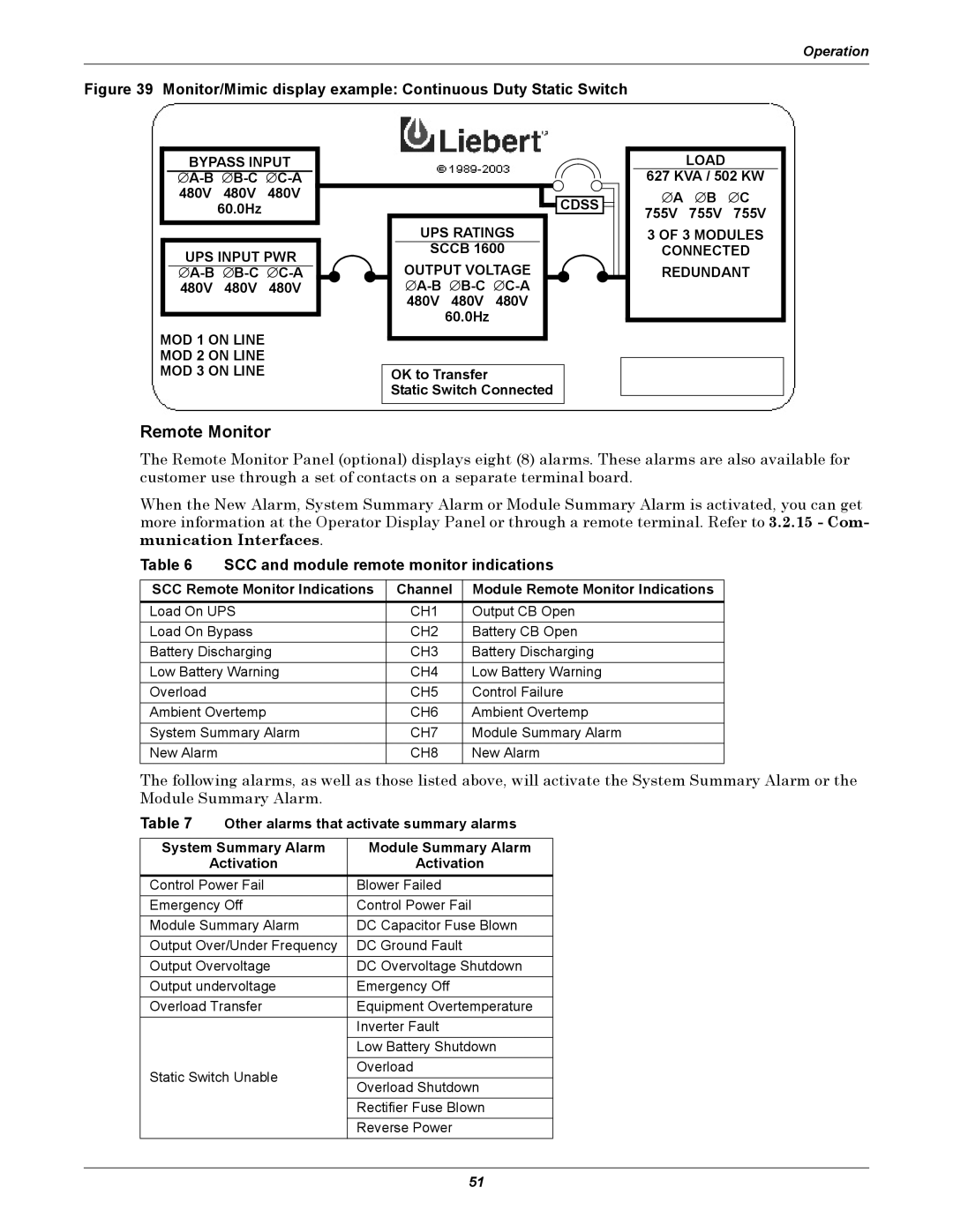
Figure 39 Monitor/Mimic display example: Continuous Duty Static Switch
BYPASS INPUT
∅
UPS INPUT PWR
∅
MOD 1 ON LINE
MOD 2 ON LINE
MOD 3 ON LINE
![]()
![]() CDSS
CDSS ![]()
UPS RATINGS
SCCB 1600
OUTPUT VOLTAGE
∅
OK to Transfer
Static Switch Connected
LOAD
627 KVA / 502 KW
∅A ∅ B ∅ C 755V 755V 755V
3 OF 3 MODULES
CONNECTED REDUNDANT
Remote Monitor
The Remote Monitor Panel (optional) displays eight (8) alarms. These alarms are also available for customer use through a set of contacts on a separate terminal board.
When the New Alarm, System Summary Alarm or Module Summary Alarm is activated, you can get more information at the Operator Display Panel or through a remote terminal. Refer to 3.2.15 - Com- munication Interfaces.
Table 6 | SCC and module remote monitor indications | ||
|
|
| |
SCC Remote Monitor Indications | Channel | Module Remote Monitor Indications | |
Load On UPS | CH1 | Output CB Open | |
Load On Bypass | CH2 | Battery CB Open | |
Battery Discharging | CH3 | Battery Discharging | |
Low Battery Warning | CH4 | Low Battery Warning | |
Overload |
| CH5 | Control Failure |
Ambient Overtemp | CH6 | Ambient Overtemp | |
System Summary Alarm | CH7 | Module Summary Alarm | |
New Alarm |
| CH8 | New Alarm |
The following alarms, as well as those listed above, will activate the System Summary Alarm or the Module Summary Alarm.
Table 7 | Other alarms that activate summary alarms | ||
|
| ||
System Summary Alarm | Module Summary Alarm | ||
| Activation | Activation | |
Control Power Fail | Blower Failed | ||
Emergency Off | Control Power Fail | ||
Module Summary Alarm | DC Capacitor Fuse Blown | ||
Output Over/Under Frequency | DC Ground Fault | ||
Output Overvoltage | DC Overvoltage Shutdown | ||
Output undervoltage | Emergency Off | ||
Overload Transfer | Equipment Overtemperature | ||
|
| Inverter Fault | |
|
| Low Battery Shutdown | |
Static Switch Unable | Overload | ||
Overload Shutdown | |||
|
| ||
|
| Rectifier Fuse Blown | |
|
| Reverse Power | |
51