Operation
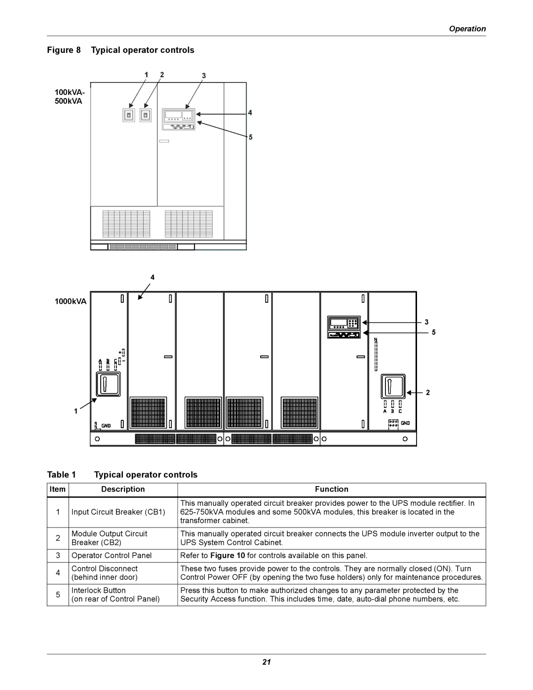
Figure 8 Typical operator controls
100kVA- |
500kVA |
5 |
2 |
5 |
4 |
1000kVA
3
5
2
1
Table 1 | Typical operator controls | |||
|
|
|
| |
Item |
| Description | Function | |
|
|
|
| |
|
|
| This manually operated circuit breaker provides power to the UPS module rectifier. In | |
1 | Input Circuit Breaker (CB1) | |||
|
|
| transformer cabinet. | |
2 | Module Output Circuit | This manually operated circuit breaker connects the UPS module inverter output to the | ||
Breaker (CB2) | UPS System Control Cabinet. | |||
| ||||
3 | Operator Control Panel | Refer to Figure 10 for controls available on this panel. | ||
|
|
| ||
4 | Control Disconnect | These two fuses provide power to the controls. They are normally closed (ON). Turn | ||
(behind inner door) | Control Power OFF (by opening the two fuse holders) only for maintenance procedures. | |||
| ||||
5 | Interlock Button | Press this button to make authorized changes to any parameter protected by the | ||
(on rear of Control Panel) | Security Access function. This includes time, date, | |||
| ||||
21