|
| TABLE OF FIGURES |
|
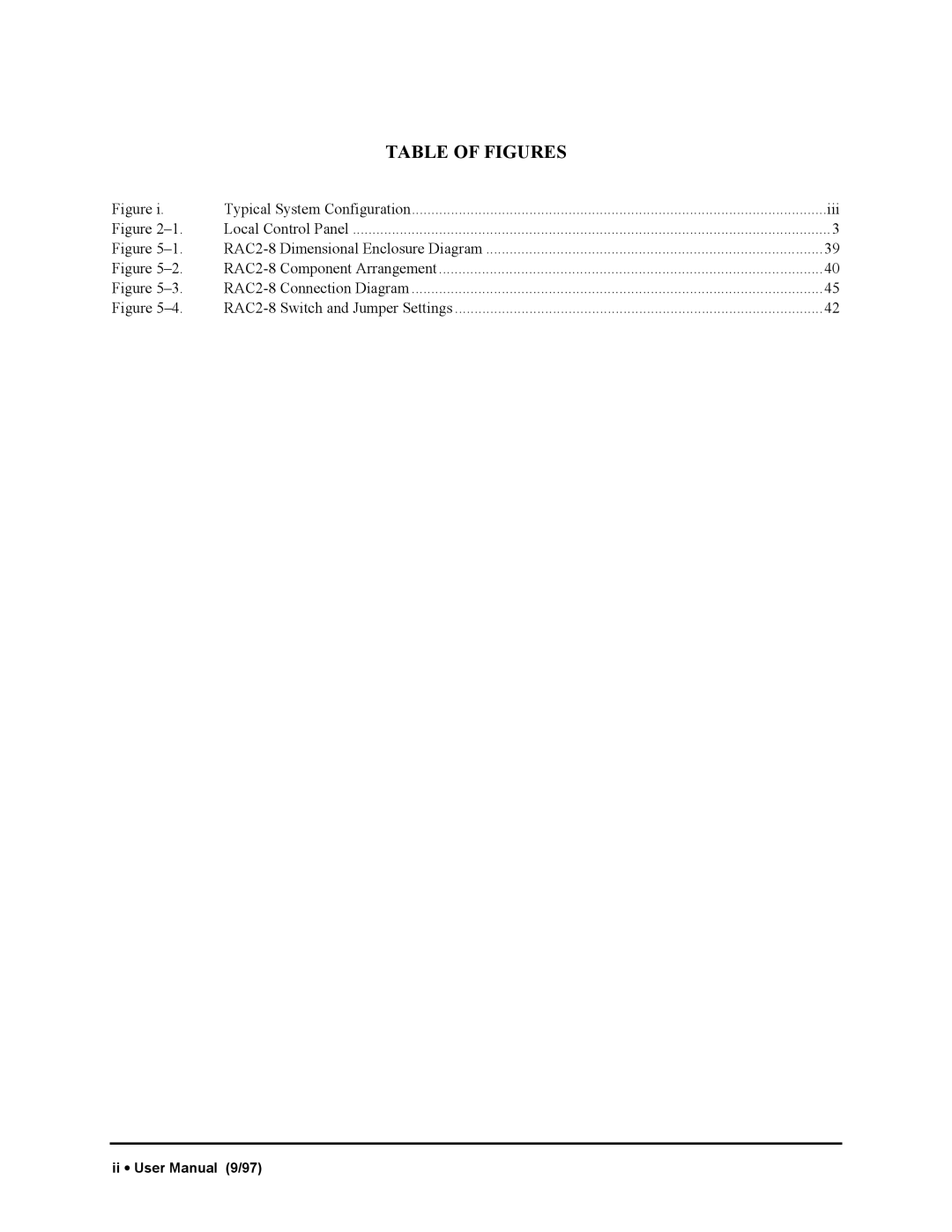
Figure i. | Typical System Configuration | iii | |
Figure | Local Control Panel | 3 | |
Figure | Dimensional Enclosure Diagram | 39 | |
Figure | Component Arrangement | 40 | |
Figure | Connection Diagram | 45 | |
Figure | Switch and Jumper Settings | 42 | |
ii • User Manual (9/97)
