Section 5: Installation
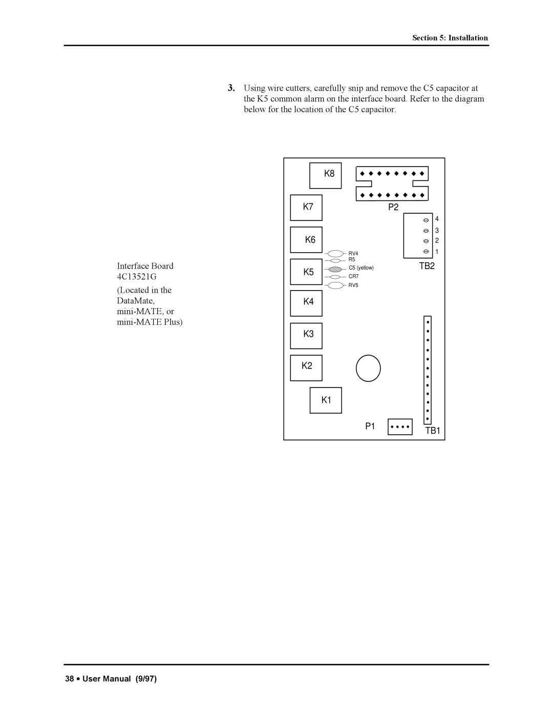
Interface Board 4C13521G
(Located in the DataMate,
3.Using wire cutters, carefully snip and remove the C5 capacitor at the K5 common alarm on the interface board. Refer to the diagram below for the location of the C5 capacitor.
K8 |
|
K7 | P2 |
| 4 |
K6 | 3 |
2 | |
RV4 | 1 |
| R5 | TB2 |
K5 | C5 (yellow) | |
CR7 |
| |
|
|
RV5
K4
K3
K2
K1
P1 | TB1 |
|
38 • User Manual (9/97)
