|
|
|
|
|
|
| INSTALLATION |
|
|
| |||||||||
|
|
|
|
|
|
|
|
|
|
|
|
|
|
|
|
|
|
|
|
AUXILIARY POWER AND CONTROL CON- |
|
|
|
|
|
| |||||||||||||
| PIN |
| LEAD NO. |
| FUNCTION | ||||||||||||||
NECTIONS |
|
|
|
|
|
|
|
|
|
|
|
|
|
|
|
| |||
|
|
|
|
|
|
|
|
|
| A |
| 32 |
| 115 VAC(3) | |||||
Located at the left side of the front of the welder |
|
|
| ||||||||||||||||
| B |
|
| GND |
| Chassis Connection | |||||||||||||
behind a hinged cover is a 115VAC duplex receptacle |
| C |
| 2 |
| Trigger Circuit | |||||||||||||
for auxiliary power (60 Hertz Models only). On the right |
| D |
| 4 |
| Trigger Circuit | |||||||||||||
side of the case front is a 14 Pin MS type receptacle |
| E |
| 77 |
| Output Control | |||||||||||||
for connection of auxiliary equipment such as wire |
| F |
| 76 |
| Output Control | |||||||||||||
feeders. Also, terminal strips with 115VAC and con- |
| G |
| 75 |
| Output Control | |||||||||||||
nections for auxiliary equipment are located behind the |
| H |
| 21 |
| (2) | |||||||||||||
hinged access panel on the right side of the case front. |
|
|
| Work Sense Connection | |||||||||||||||
| I |
| 41 |
| 42 VAC | ||||||||||||||
(see Auxiliary Power Table for details) |
|
|
|
|
|
|
|
| |||||||||||
|
|
|
|
|
| J |
| 31 |
| 115 VAC(3) | |||||||||
|
|
| AUXILIARY POWER TAbLE |
|
|
|
| K |
| 42 |
| 42 VAC | |||||||
Voltage and Circuit Breaker Ratings at Auxiliary Power |
|
|
| ||||||||||||||||
| L |
|
| ||||||||||||||||
|
|
| Connections for Various Models |
|
|
|
|
|
| ||||||||||
|
|
|
|
|
|
| M |
|
| ||||||||||
|
|
|
|
|
|
|
|
|
|
|
|
|
|
|
| ||||
Table for Codes 11598, 11613 |
| Table for Codes 11707, 11725 |
|
| N |
|
| ||||||||||||
|
|
|
|
|
|
|
|
|
|
|
|
|
|
|
| ||||
Auxiliary |
| 60 Hz |
| 50/60 Hz |
| Auxiliary | 60 Hz |
| 50/60 Hz |
|
|
|
|
|
|
|
| ||
Power |
| Models |
| Models |
| Power | Models |
| Models |
|
|
|
|
|
|
|
| ||
Connections |
|
|
|
|
| Connections |
|
|
|
|
| TERMINAL STRIPS |
| ||||||
|
|
|
|
|
|
|
|
|
|
|
|
|
| ||||||
|
|
|
|
|
|
|
|
|
|
|
|
|
| ||||||
At Duplex |
| 15A |
| No Duplex |
| At Duplex | 15A |
| No Duplex |
|
|
|
|
|
|
|
| ||
Receptacle |
| 115V |
|
|
| Receptacle | 115V |
|
|
|
| Terminal strips are available behind the cover on the | |||||||
|
|
|
|
|
|
|
|
|
|
|
|
| |||||||
Terminal strip |
| 115V 15A | 115V 15A |
| Terminal strip | 115V 15A | 115V 15A |
| case front to connect wire feeder control cables that | ||||||||||
terminals 31 & 32 |
|
|
|
| terminals 31 & 32 |
|
|
|
|
| do not have a 14 Pin | ||||||||
| 115V 15A | 115V 15A |
| 42V 10A |
| 42V 10A |
| nals supply the connections as shown in the following | |||||||||||
|
|
|
|
|
|
|
|
|
|
| |||||||||
pins A & J |
|
|
|
|
| pins I & K |
|
|
|
|
| Terminal Strip charts. NOTE: There are two work | |||||||
|
|
|
|
|
|
|
|
|
|
|
|
| sense lead connection points on the terminal strip. | ||||||
| 42V 10A |
| 42V 10A |
|
|
|
|
|
|
| |||||||||
|
|
|
|
|
|
|
|
| Connect both the work sense lead #21 from the 14 pin | ||||||||||
pins I & K |
|
|
|
|
|
|
|
|
|
|
| ||||||||
|
|
|
|
|
|
|
|
|
|
|
|
| connector and #21 lead of the control cable to | ||||||
115VAC DUPLEX RECEPTACLE (60 HERTz | when welding positive polarity or to “+21” when weld- | ||||||||||||||||||
MODELS ONLY) |
|
|
|
|
|
|
|
|
| ing negative polarity. |
| ||||||||
The 115VAC duplex receptacle is protected by a 15 |
|
| TERMINAL STRIP 1 (T.S.1) | ||||||||||||||||
Amp circuit breaker located on the nameplate. The |
|
| |||||||||||||||||
receptacle is a NEMA |
|
|
|
|
|
| Lead No. |
| Function | ||||||||||
|
|
|
|
|
|
|
|
|
|
|
| ||||||||
14 PIN MS TYPE RECEPTACLE |
|
|
|
|
|
|
|
|
|
|
|
| |||||||
|
|
|
|
|
|
|
| 75 |
|
| Output Control | ||||||||
(For |
| L.E.C. Part |
|
|
|
|
| ||||||||||||
|
|
|
| 76 |
|
| Output Control | ||||||||||||
|
|
|
|
|
|
|
|
|
|
|
|
|
|
|
|
|
| ||
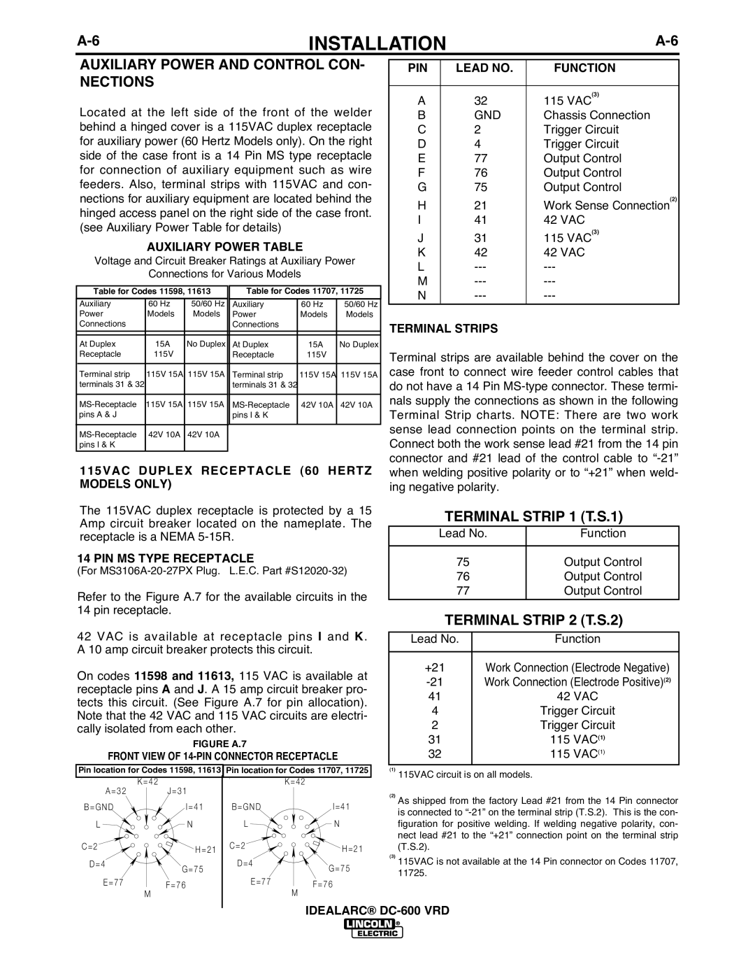
Refer to the Figure A.7 for the available circuits in the |
|
|
| 77 |
|
| Output Control | ||||||||||||
|
|
|
|
|
|
| |||||||||||||
|
|
|
|
|
|
| |||||||||||||
14 pin receptacle. |
|
|
|
|
|
|
|
|
|
|
| TERMINAL STRIP 2 (T.S.2) | |||||||
|
|
|
|
|
|
|
|
|
|
|
|
|
|
| |||||
42 VAC is available at receptacle pins I and K. |
|
|
|
|
|
| |||||||||||||
| Lead No. |
|
| Function | |||||||||||||||
A 10 amp circuit breaker protects this circuit. |
|
|
|
|
|
|
|
|
|
| |||||||||
|
|
|
| +21 |
| Work Connection (Electrode Negative) | |||||||||||||
On codes 11598 and 11613, 115 VAC is available at |
|
| |||||||||||||||||
|
| Work Connection (Electrode Positive)(2) | |||||||||||||||||
receptacle pins A and J. A 15 amp circuit breaker pro- |
| 41 |
|
|
| 42 VAC | |||||||||||||
tects this circuit. (See Figure A.7 for pin allocation). |
|
|
|
| |||||||||||||||
| 4 |
|
|
|
| Trigger Circuit | |||||||||||||
Note that the 42 VAC and 115 VAC circuits are electri- |
|
|
|
|
| ||||||||||||||
| 2 |
|
|
|
| Trigger Circuit | |||||||||||||
cally isolated from each other. |
|
|
|
|
|
|
|
|
|
| |||||||||
|
|
|
|
|
| 31 |
|
|
| 115 VAC(1) | |||||||||
|
|
|
|
| FIGURE A.7 |
|
|
|
|
|
|
|
|
| |||||
|
|
|
|
|
|
|
|
|
|
| 32 |
|
|
| 115 VAC(1) | ||||
FRONT VIEW OF |
|
|
|
|
|
|
| ||||||||||||
|
|
|
|
|
|
|
|
|
|
|
|
|
|
|
|
| |||
Pin location for Codes 11598, 11613 | Pin location for Codes 11707, 11725 |
| (1) | 115VAC circuit is on all models. |
| ||||||||||||||
|
|
|
|
|
|
|
|
|
|
|
|
|
|
| |||||
|
| K=42 |
|
|
| K=42 |
|
|
|
|
|
|
|
|
|
| |||
A=32 |
| J=31 |
|
|
|
|
|
|
| (2) As shipped from the factory Lead #21 from the 14 Pin connector | |||||||||
B=GND |
|
|
| I=41 |
| B=GND | I=41 | ||||||||||||
|
|
|
|
| is connected to | ||||||||||||||
|
|
|
|
|
|
|
|
|
|
|
|
|
| ||||||
L |
|
|
| N |
| L | N |
|
|
|
| figuration for positive welding. If welding negative polarity, con- | |||||||
|
|
|
|
|
|
|
|
|
|
|
|
|
| nect lead #21 to the “+21” connection point on the terminal strip | |||||
C=2 |
|
|
| H=21 |
| C=2 |
|
| H=21 |
| (T.S.2). |
|
|
|
| ||||
D=4 |
|
| G=75 |
| D=4 | G=75 | (3) 115VAC is not available at the 14 Pin connector on Codes 11707, | ||||||||||||
|
|
|
|
|
|
| 11725. |
|
|
|
|
| |||||||
E=77 |
|
|
|
|
| E=77 |
|
|
|
|
|
|
|
|
|
|
| ||
| F=76 |
| F=76 |
|
|
|
|
|
|
|
|
|
| ||||||
|
| M |
|
|
| M |
|
|
|
|
|
|
|
|
|
|
|
| |
|
|
|
|
|
|
|
| IDEALARC® |
|
|
|
| |||||||
|
|
|
|
|
|
|
|
|
|
|
| ||||||||