OPERATION | ||
|
|
|
OVERLOAD, OVERCURRENT, AND FAULT PROTECTION
This welder has thermostatic protection from exces- sive duty cycles, overloads, loss of cooling, and high ambient temperatures. When the welder is subjected to an overload or loss of cooling, a thermostat will open. The input contactor will open and remain open until the machine cools; the white POWER light stays illuminated. No welding is possible during this cool down period. The machine will reset automatically when the thermostat cools.
The power source is also protected against overcur- rents in the SCR bridge assembly through an elec- tronic protection circuit. This circuit senses currents over 780 amps on the power source and opens the input contactor should the overcurrent remain for a predetermined time (the white POWER light also turns off).
The predetermined time varies with the amount of overcurrent; the greater the overcurrent, the shorter the time. The input contactor will remain open until the power source is manually started by resetting the POWER ON/OFF toggle switch.
For codes 11707 and above.
The power source is protected against overvoltage when not welding in CC mode. If the protection circuit senses voltage in excess of 49V at the studs when no welding is taking place, the POWER light will turn off. The input contactor will open up and remain open until the power source is manually restarted by toggling the ON/OFF switch.
The power source circuitry is protected from faults on leads 75, 76, or 77. If any of these leads are connect- ed to either the positive or negative output leads, the IDEALARC®
VRD (VOLTAGE REDUCTION DEVICE) OPERATION
The VRD electronic circuitry is designed to reduce the OCV of the power source in the Constant Current
(CC)Stick welding mode only. The operation of the machine with the VRD is slightly different than the operation of a standard machine. The following describes the machine operation with the VRD installed in the DC600.
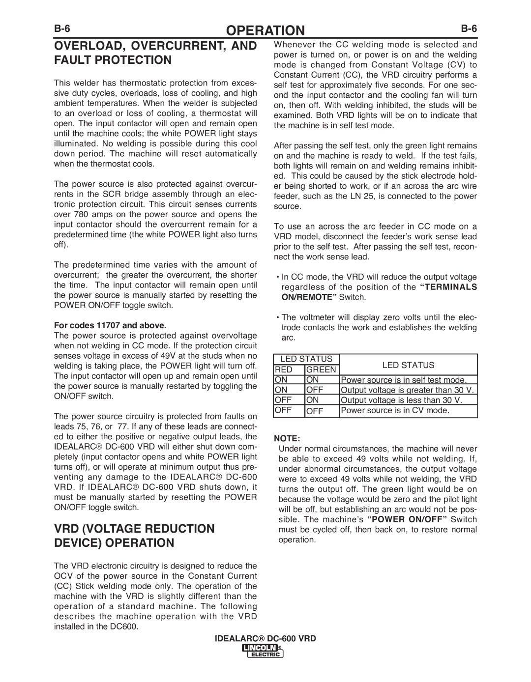
Whenever the CC welding mode is selected and power is turned on, or power is on and the welding mode is changed from Constant Voltage (CV) to Constant Current (CC), the VRD circuitry performs a self test for approximately five seconds. For one sec- ond the input contactor and the cooling fan will turn on, then off. With welding inhibited, the studs will be examined. Both VRD lights will be on to indicate that the machine is in self test mode.
After passing the self test, only the green light remains on and the machine is ready to weld. If the test fails, both lights will remain on and welding remains inhibit- ed. This could be caused by the stick electrode hold- er being shorted to work, or if an across the arc wire feeder, such as the LN 25, is connected to the power source.
To use an across the arc feeder in CC mode on a VRD model, disconnect the feeder’s work sense lead prior to the self test. After passing the self test, recon- nect the work sense lead.
•In CC mode, the VRD will reduce the output voltage regardless of the position of the “TERMINALS ON/REMOTE” Switch.
•The voltmeter will display zero volts until the elec- trode contacts the work and establishes the welding arc.
LED STATUS | LED STATUS | ||
RED | GREEN | ||
| |||
ON | ON | Power source is in self test mode. | |
ON | OFF | Output voltage is greater than 30 V. | |
OFF | ON | Output voltage is less than 30 V. | |
OFF | OFF | Power source is in CV mode. | |
|
|
| |
NOTE:
Under normal circumstances, the machine will never be able to exceed 49 volts while not welding. If, under abnormal circumstances, the output voltage were to exceed 49 volts while not welding, the VRD turns the output off. The green light would be on because the voltage would be zero and the pilot light will be off, but establishing an arc would not be pos- sible. The machine’s “POWER ON/OFF” Switch must be cycled off, then back on, to restore normal operation.
IDEALARC®
