Return to Section TOC
Return to Master TOC
| TROUBLESHOOTING & REPAIR |
AMPS/VOLTS DIGITAL METER AND POTENTIOMETER
REMOVAL AND REPLACEMENT (CONTINUED)
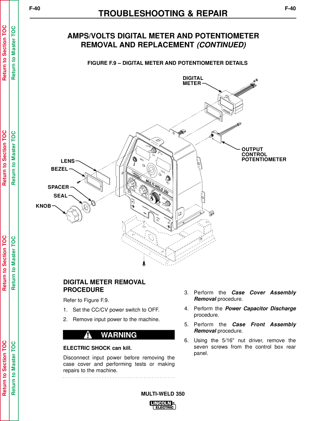
FIGURE F.9 – DIGITAL METER AND POTENTIOMETER DETAILS
DIGITAL
METER![]()
Return to Section TOC
Return to Master TOC
LENS
BEZEL
SPACER SEAL
KNOB
3
2
|
|
|
|
|
|
| CC |
|
|
|
|
|
|
|
|
|
|
|
|
|
|
|
|
|
| OFF |
| CV |
|
|
|
|
|
|
|
|
|
|
|
|
|
|
|
|
|
|
|
|
|
|
|
| |
|
|
|
| AMPS |
|
|
|
|
|
|
|
|
|
|
|
| |
|
|
|
|
| A |
|
|
|
|
|
|
|
|
|
|
|
|
|
| LINCOLN |
|
|
|
|
| V | VOLTS |
|
|
|
| ||||
|
| ELECTRIC |
|
|
|
|
|
|
|
|
|
|
|
| |||
4 | 5 |
|
|
|
|
|
|
|
|
|
|
|
|
| |||
|
| 6 |
|
|
|
| MULTI- |
|
|
|
|
|
|
|
|
| |
|
|
| 8 |
|
|
|
|
|
|
|
|
|
|
|
| ||
|
|
| 7 |
|
|
|
| WELD |
|
|
|
|
|
|
| ||
| STA |
| 4 | 2 | 0 |
|
|
|
|
|
|
|
| ||||
HOT |
| RT |
| 6 |
|
| 2 |
|
|
|
|
|
|
|
|
|
|
| 10 | 9 |
|
|
| 4 |
|
|
| 350 |
|
| |||||
|
|
|
|
|
|
|
|
|
|
| |||||||
|
|
|
|
|
|
| RCE | 6 |
|
|
|
| |||||
|
|
|
|
| ARC | FO 10 |
|
| S | TIC | K |
|
|
|
| ||
INPUT |
|
|
|
|
|
| 8 |
|
| ||||||||
|
|
|
|
|
|
|
|
| 701 | L111 |
| ||||||
|
|
|
|
|
|
|
|
|
|
|
|
| |||||
|
|
|
|
|
|
|
|
|
| GOUGE |
| ||||||
|
|
|
|
|
|
|
| O |
| PIP | E |
|
|
|
|
| |
|
|
|
|
|
|
|
|
|
|
|
|
|
|
| |||
|
|
|
|
|
|
|
| TE |
|
|
|
|
|
|
|
|
|
|
|
|
|
| CHOPPER |
|
|
|
|
|
|
| CC |
| |||
|
|
|
|
|
|
|
| TECHNOLOGY |
|
|
|
|
| SLOPE |
| ||
|
|
|
|
|
|
|
|
|
|
| ELECTR |
|
| ||||
|
|
|
|
|
|
|
| WO | RK |
|
|
|
|
| |||
|
|
|
|
|
|
|
|
|
|
|
|
|
|
|
| ODE |
|
![]() OUTPUT CONTROL POTENTIOMETER
OUTPUT CONTROL POTENTIOMETER
Return to Section TOC
Return to Section TOC
Return to Master TOC
Return to Master TOC
DIGITAL METER REMOVAL
PROCEDURE
Refer to Figure F.9.
1.Set the CC/CV power switch to OFF.
2.Remove input power to the machine.
WARNING
ELECTRIC SHOCK can kill.
Disconnect input power before removing the case cover and performing tests or making repairs to the machine.
3.Perform the Case Cover Assembly Removal procedure.
4.Perform the Power Capacitor Discharge procedure.
5.Perform the Case Front Assembly Removal procedure.
6.Using the 5/16" nut driver, remove the seven screws from the control box rear panel.
