Return to Section TOC
Return to Master TOC
| TROUBLESHOOTING & REPAIR |
ANALOG CONTROL POWER SUPPLY PC BOARD TEST (CONTINUED)
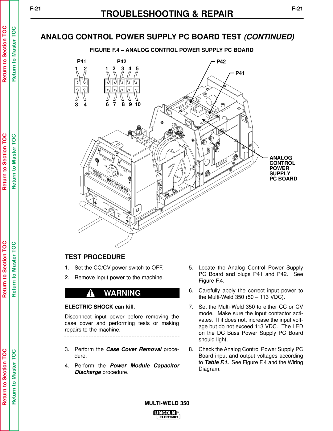
FIGURE F.4 – ANALOG CONTROL POWER SUPPLY PC BOARD
P41 |
|
| P42 |
| P42 | |
1 | 2 | 1 | 2 | 3 | 4 | 5 |
P41
3 4 6 7 8 9 10
Return to Section TOC
Return to Master TOC
AMPS |
|
|
|
|
A |
|
|
|
|
LINCOLN |
|
|
| VOLTS |
|
| V |
| |
ELECTRIC |
|
|
|
|
MULTI- |
|
| ||
|
| WELD | 350 | |
|
|
|
| |
INPUT |
|
|
|
|
CHOPPER | T | ECHNOLOGY |
|
|
|
|
| ||
|
| WORK |
| ELECTRODE |
ANALOG CONTROL POWER SUPPLY PC BOARD
Return to Section TOC
Return to Section TOC
Return to Master TOC
Return to Master TOC
TEST PROCEDURE
1.Set the CC/CV power switch to OFF.
2.Remove input power to the machine.
WARNING
ELECTRIC SHOCK can kill.
Disconnect input power before removing the case cover and performing tests or making repairs to the machine.
3.Perform the Case Cover Removal proce- dure.
4.Perform the Power Module Capacitor Discharge procedure.
5.Locate the Analog Control Power Supply PC Board and plugs P41 and P42. See Figure F.4.
6.Carefully apply the correct input power to the
7.Set the
8.Check the Analog Control Power Supply PC Board input and output voltages according to Table F.1. See Figure F.4 and the Wiring Diagram.