OPERATION
Return to Section TOC
Return to Section TOC
Return to Section TOC
Return to Section TOC
Return to Master TOC
Return to Master TOC
Return to Master TOC
Return to Master TOC
Disconnecting the Remote plug from this recepta- cle automatically transfers output control back to the panel Output Control (item (2) above).
Remote output On/Off switching can also be done through this Remote Control receptacle by per- forming the following wiring changes:
1.Making sure the input to the Converter is removed, remove the case wraparound.
2.Locate the
3.Replace the case wraparound.
4.Connect a
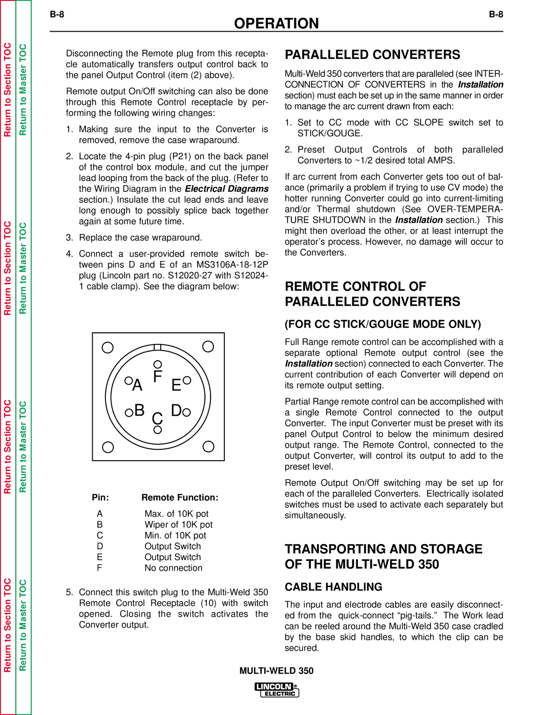
1 cable clamp). See the diagram below:
A F E
B C D
Pin: | Remote Function: |
AMax. of 10K pot
BWiper of 10K pot
CMin. of 10K pot
DOutput Switch
EOutput Switch
FNo connection
5.Connect this switch plug to the
PARALLELED CONVERTERS
1.Set to CC mode with CC SLOPE switch set to
STICK/GOUGE.
2.Preset Output Controls of both paralleled Converters to ~1/2 desired total AMPS.
If arc current from each Converter gets too out of bal- ance (primarily a problem if trying to use CV mode) the hotter running Converter could go into
REMOTE CONTROL OF PARALLELED CONVERTERS
(FOR CC STICK/GOUGE MODE ONLY)
Full Range remote control can be accomplished with a separate optional Remote output control (see the Installation section) connected to each Converter. The current contribution of each Converter will depend on its remote output setting.
Partial Range remote control can be accomplished with a single Remote Control connected to the output Converter. The input Converter must be preset with its panel Output Control to below the minimum desired output range. The Remote Control, connected to the output Converter, will control its output to add to the preset level.
Remote Output On/Off switching may be set up for each of the paralleled Converters. Electrically isolated switches must be used to activate each separately but simultaneously.
TRANSPORTING AND STORAGE OF THE MULTI-WELD 350
CABLE HANDLING
The input and electrode cables are easily disconnect- ed from the