Return to Section TOC
Return to Master TOC
INSTALLATION | ||
|
POWER SOURCE TO LN-25™ PRO
CABLE CONNECTION DIAGRAMS
ACROSS THE ARC SET-UPS
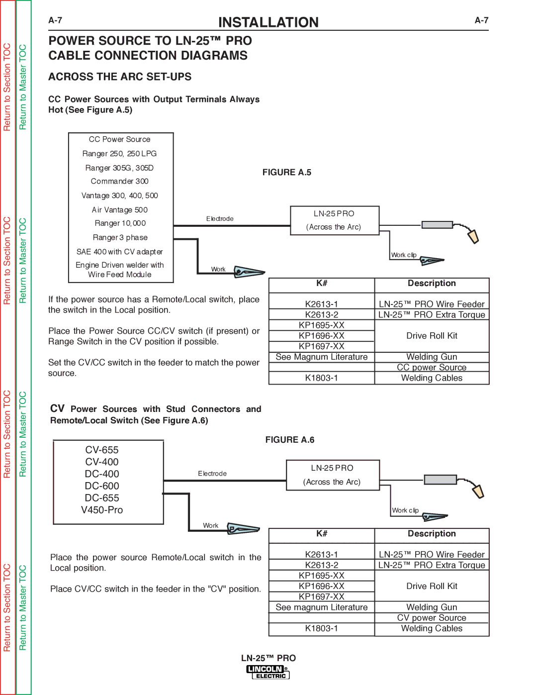
CCPower Sources with Output Terminals Always Hot (See Figure A.5)
CCPower Source Ranger 250, 250 LPG Ranger 305G, 305D
Commander 300
Vantage 300, 400, 500
Air Vantage 500
FIGURE A.5
TOC
TOC
Ranger 10,000
Electrode
(Across the Arc)
Return to Master
Ranger 3 phase
SAE 400 with CV adapter
Engine Driven welder with
Work
Wire Feed Module
If the power source has a Remote/Local switch, place the switch in the Local position.
Place the Power Source CC/CV switch (if present) or Range Switch in the CV position if possible.
Set the CV/CC switch in the feeder to match the power source.
| Work clip |
|
|
K# | Description |
|
|
| |
Drive Roll Kit | |
| |
See Magnum Literature | Welding Gun |
| CC power Source |
Welding Cables | |
|
|
Section TOC
Master TOC
CV Power Sources with Stud Connectors and Remote/Local Switch (See Figure A.6)
Return to
Return to Section TOC
Return to
Return to Master TOC
DC-600
DC-655
V450-Pro
Work
Place the power source Remote/Local switch in the Local position.
Place CV/CC switch in the feeder in the "CV" position.
FIGURE A.6
(Across the Arc)
| Work clip |
|
|
K# | Description |
|
|
| |
Drive Roll Kit | |
| |
See magnum Literature | Welding Gun |
| CV power Source |
Welding Cables | |
|
|