Return to Section TOC
Return to Section TOC
Return to Section TOC
Return to Section TOC
Return to Master TOC
Return to Master TOC
Return to Master TOC
Return to Master TOC
TROUBLESHOOTING & REPAIR | ||
|
CONTACTOR REMOVAL AND REPLACEMENT PROCEDURE (CONTINUED)
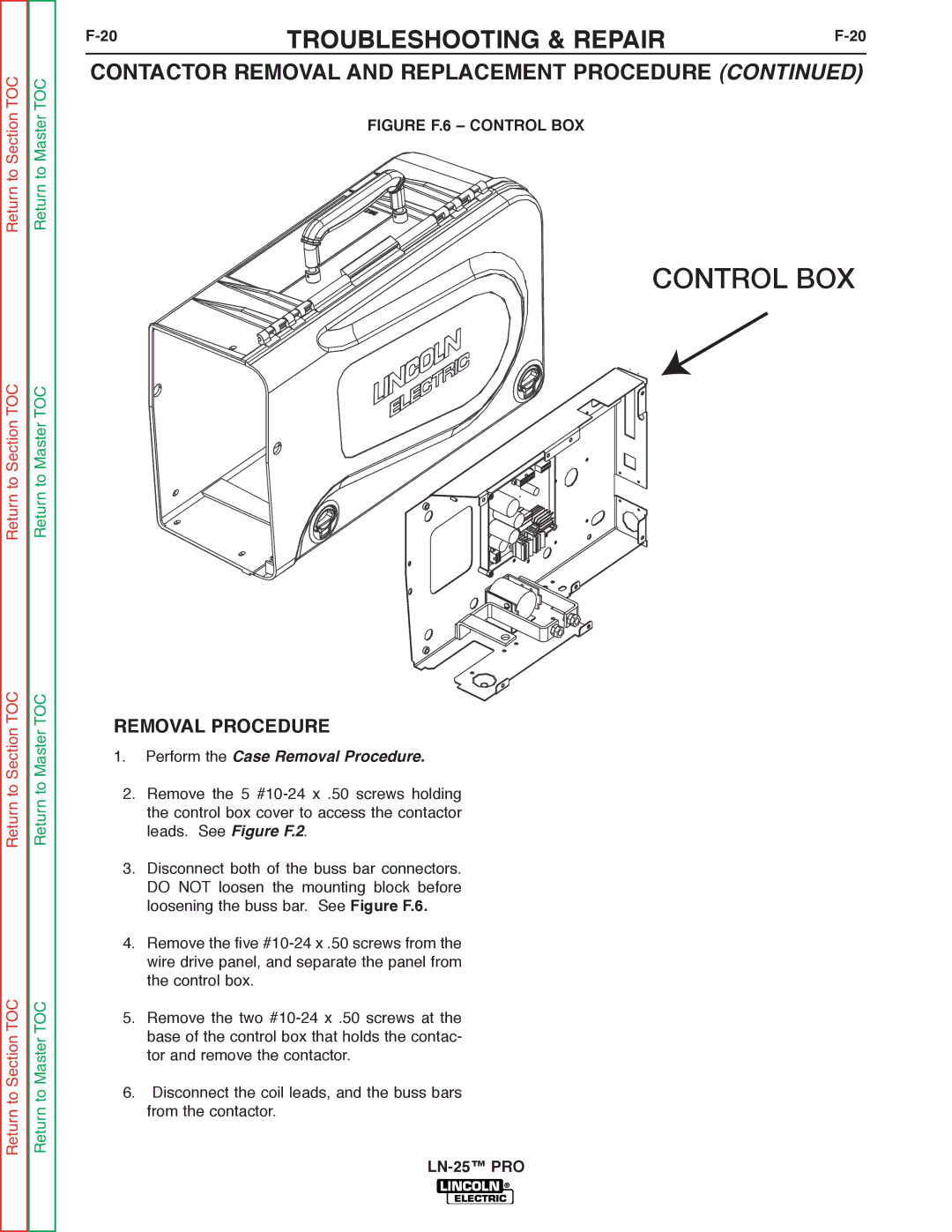
FIGURE F.6 – CONTROL BOX
CONTROL BOX
REMOVAL PROCEDURE
1.Perform the Case Removal Procedure.
2.Remove the 5
3.Disconnect both of the buss bar connectors. DO NOT loosen the mounting block before loosening the buss bar. See Figure F.6.
4.Remove the five
5.Remove the two
6.Disconnect the coil leads, and the buss bars from the contactor.