Return to Section TOC
Return to Section TOC
TOC
Return to Master TOC
Return to Master TOC
TOC
TROUBLESHOOTING & REPAIR | ||
|
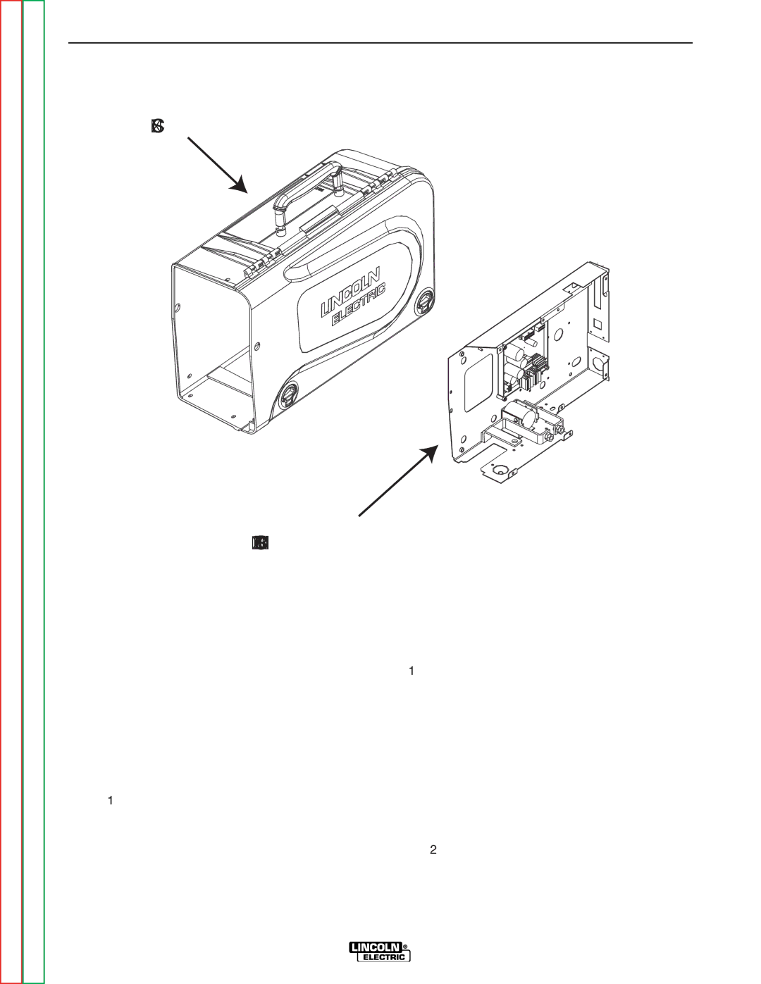
DRIVE MOTOR AND TACH FEEDBACK TEST (CONTINUED)
FIGURE F.4 – CONTROL BOX ASSEMBLY
CASE
CONTROL BOX ASSEMBLY
PROCEDURE
Return to Section
Return to Section TOC
Return to Master
Return to Master TOC
1.Perform the Case Removal Procedure.
2.Remove the 5
3.Remove the 5
4.Apply the correct input voltage
5.With trigger activated and the motor running check for 2.6VDC min. to 32VDC max. between the black and white motor leads (pins 7 and 8).
NOTE: If the tach feedback is missing the board will limit the motor voltage to 10VDC no matter where the w/s pot is set.
6.Check for 1.5 ohms of resistance between the black and white leads. Also make sure there is at least 550k ohms of resistance between both leads and the motor shell.
7.With the trigger activated and the motor run- ning check for 15.6VDC input on the black and red tach leads. Check for 6.2vdc at any speed or ≈72hz (min.). to ≈1.2Khz (max). on the black and blue return leads.
8.For further testing on the drive motor you can use an isolated source and apply between 2.6VDC and 32VDC to the motor leads.
9.If all the above voltages are not there the motor or tach needs to be replaced. See Wire
Drive Motor and Gear Box Removal and Replacement.